10
Description of Safety Functions Section 1-4
1-4-2 Safety Inputs
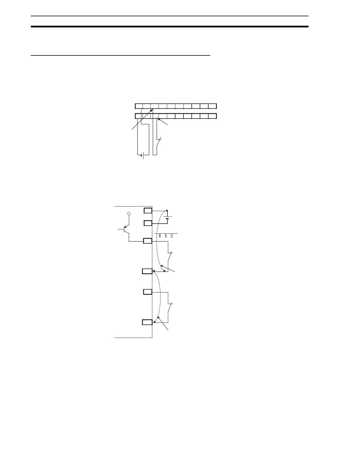
Safety Inputs with Test Pulses (Input Circuit Diagnosis)
A test output is used in combination with a safety input. Specify the corre-
sponding test output terminal to use as the test source. The test output termi-
nal is used as a power supply to connect an external input device to the safety
input terminal.
A test pulse is output from the test output terminal to diagnose the internal cir-
cuit when the external input contact turns ON. Using this function, short-cir-
cuits between input signal lines and the power supply (positive side), and
short-circuits between input signal lines can be detected.
V V 0 1 2 3 4 5 6 7
G G T0 T1 T0 T1 T0 T1 T0 T1
Example: DST1-ID12S-1
24 V
Here, IN0 and T0 are used in combination,
24 V DC output with test pulse
External contact
Safety input
terminal
External contact
T0
IN0
24 V
0 V
24 V
External contact
T1
IN1
Short-circuit between input signal line and
power supply (positive side)
Short-circuit between input signal lines
V
G

 Loading...


