108
DST1-XD0808SL-1 Section 5-4
Note Power supply terminal V1 for the output devices is internally monitored. Sup-
ply the voltage in the specified range (20.4 to 26.4 VDC). If the voltage is sup-
plied outside this range, voltage will not be supplied to the output circuits.
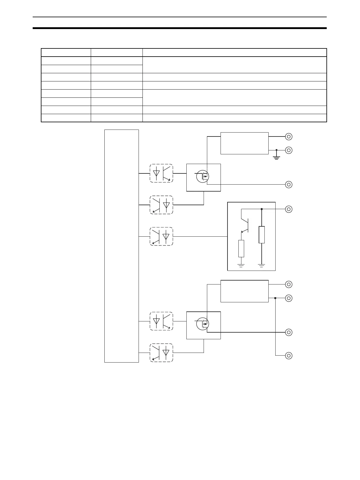
Terminals Names Functions
1, 2 V0 Power terminals for input devices and test outputs (24 VDC)
11, 12 G0
3 to 10 IN0 to IN7 Terminals for safety inputs
13 to 20 T0 to T3 Terminals for test outputs
21, 22 V1 Power terminals for output devices (24 VDC)
31, 32 G1
23 to 30 OUT0 to OUT7 Terminals for safety outputs
33 to 40 G1 Common terminals. Terminals 31 to 40 are internally connected.
I/O Power Supply
Circuit
Internal
Circuit
Test Output Circuit
Safety Input Circuit
V0
V0+
G0
T0...T3
IN0...IN7
I/O Power Supply
Circuit
Safety Output Circuit
V1
V1+
G1
OUT0
...OUT7
G1

 Loading...


