49
Connecting I/O Power and I/O Cable Section 2-3
Reference Specifications (Product Specifications from Phoenix Contact)
Crimping Tool for Ferrules
IMPORTANT • I/O connectors are detachable. Tighten the screws on the I/O connector
to 0.25 to 0.3 N·m.
• Separate I/O signal cables from high-voltage lines and power lines.
• I/O signal cables must be no longer than 30 m.
• Do not apply power to safety output terminals or test output terminals.
Doing so may cause burning or other damage to the product.
• Do not remove the label from the DST1 before wiring.
• Always remove the label after completing wiring to ensure proper heat
dispersion.
Model of ferrule Wire dimensions Ferrule specifications
Cross-
sectional
area of
conductor
(mm
2
)
AWG Removed
length of
insulation
(mm)
Overall
length
L1 (mm)
Length of
metal part
L2 (mm)
Inner
diameter of
conductor
D1 (mm)
Inner
diameter of
insulation
cover D2
(mm)
Dimensions
For one wire
AI 0,34-8TQ 0.34 22 10 12.5 8 0.8 2.0 *1
AI 0,5-10WH 0.5 20 10 16 10 1.1 2.5
AI 0,75-10GY 0.75 18 10 16 10 1.3 2.8
AI 1-10RD 1.0 18 10 16 10 1.5 3.0
AI 1,5-10BK 1.5 16 10 18 10 1.8 3.4
For two wires
AI-TWIN
2 x 0,75-10GY
2 x 0.75 - 10 17 10 1.8 2.8/5.0 *2
AI-TWIN
2 x 1-10RD
2 x 1 - 10 17 10 2.05 3.4/5.4
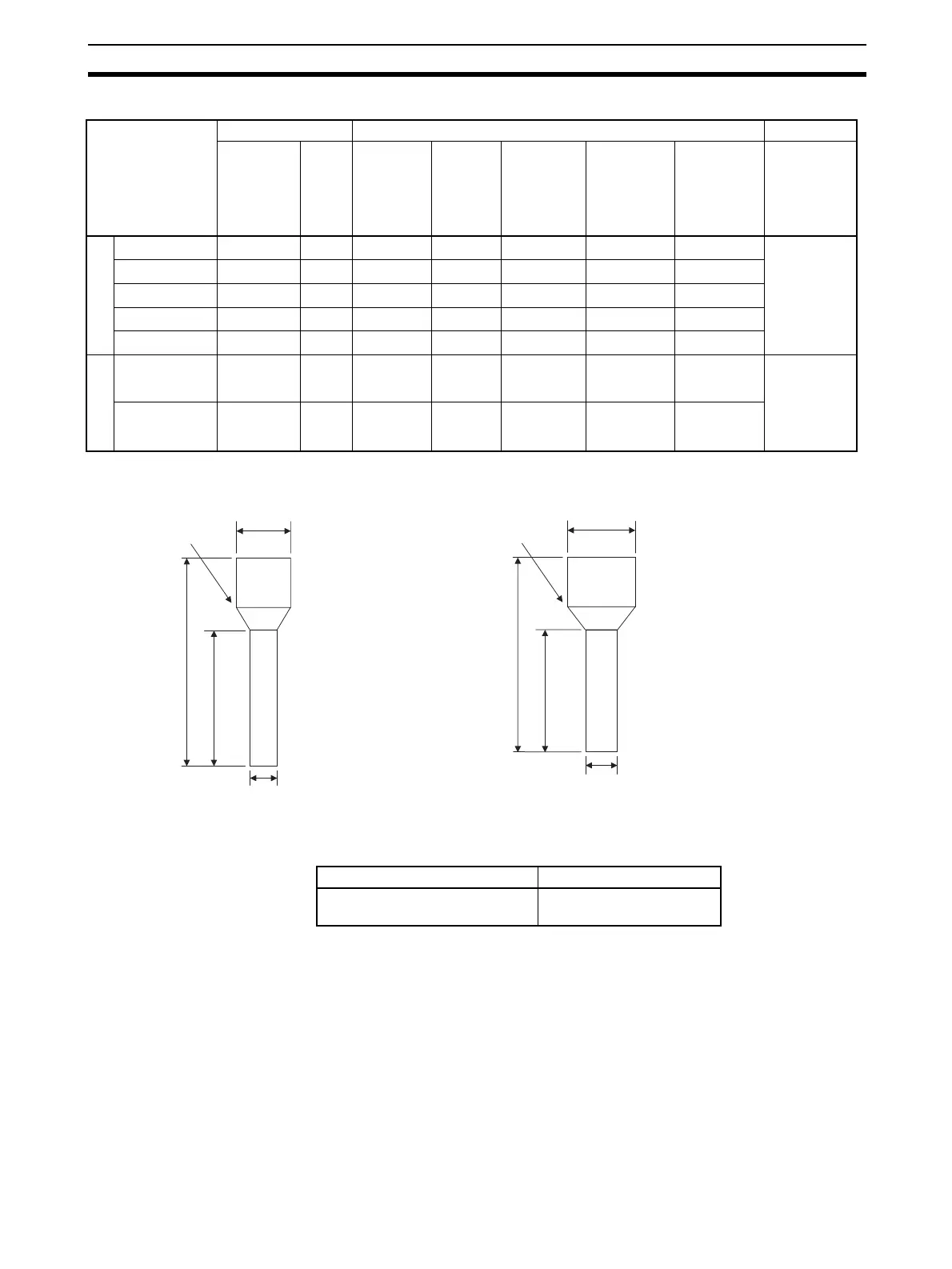
* 1 For One Wire * 2 For Two Wires
Dia. D2
L2
Dia. D1
Insulating collar
L1
Dia. D2
L2
Dia. D1
Insulating collar
L1
Manufacturer Model
Phoenix Contact CRIMPFOX UD6
or CRIMPFOX ZA3

 Loading...


