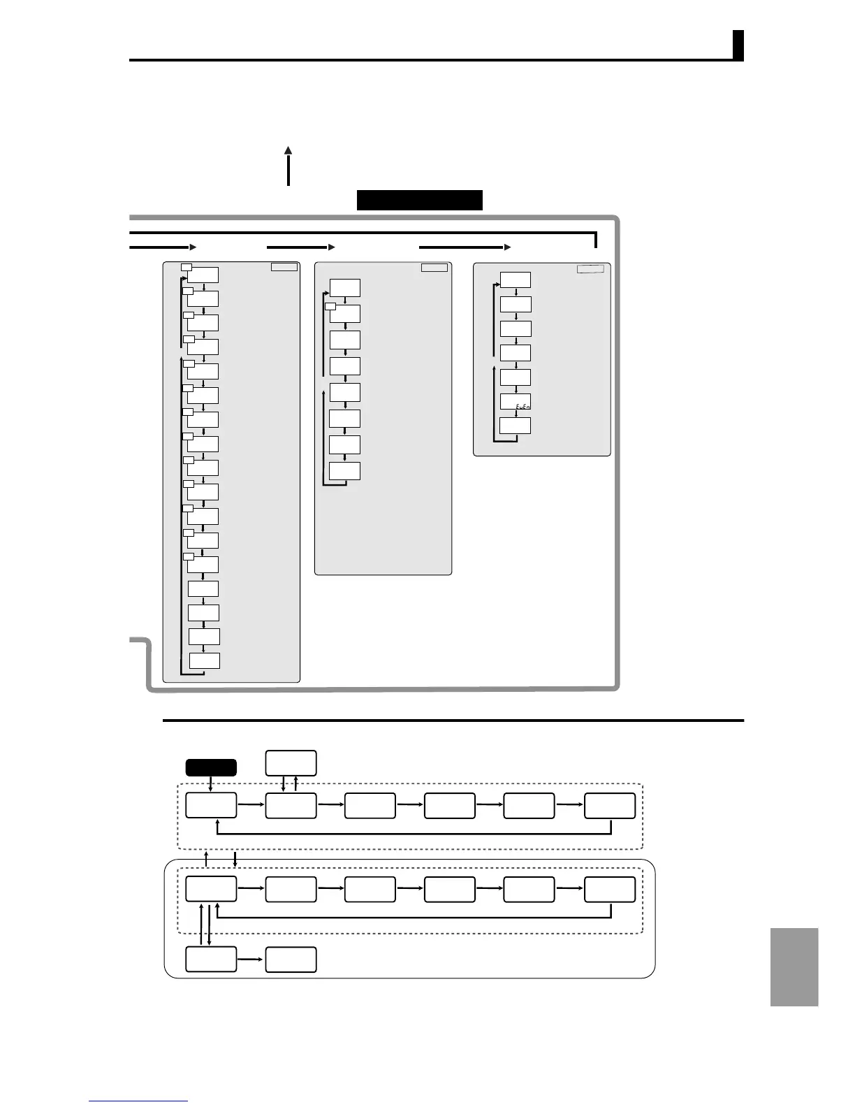
Setting data list
A-33
Appendix
M
M
M
M
M
M
M
M
M
M
M
M
M
l.3
M
M
M
M
n-o
sb1n
alt1
2
off
a1lt
alh1
0.02
alt2
2
sb2n
n-o
a2lt
off
alh2
0.02
alt3
2
n-o
sb3n
off
a3lt
alh3
0.02
alt4
2
n-o
sb4n
off
a4lt
alh4
0.02
rest
a
CH
CH
CH
CH
CH
CH
CH
CH
CH
CH
CH
CH
CH
M
M
M
M
M
M
l.4
M
M
spdp
1
odsl
o
bart
o
0
ret
d.ref
0. 5
monl
off
sc-m
off
sc-t
2
CH
M
M
M
M
M
M
M
l.5
psel
cwf
1
u-no
bps
9.6
len
7
sbit
2
prty
sdwt
20
See page A-30 to input initial setting level
Control starts
L
key 1 second or more
L
less than 1 second
L
less than 1 second
Adjustment
level
Protect level
Operation
Level
Adjustment 2
level
PID setting
level
Bank setting
level
Approximation
setting level
Control initial
setting level
Input initial
setting level
Control initial
setting 2 level
Display adjustment
level
Alarm setting
level
Communication
setting level
Special function
setting level
Expansion control
setting level
Power on
Alarm
Setting Level
Display
Adjustment Level
Communication
Setting Level
ALT1:
Alarm 1 type
0-11
SB1N: Auxiliary output
1 non-exciting
Close in alarm: N-O /
Open in alarm: N-C
ALH1:
Alarm 1 hysteresis
0.01-99.99
ALH2:
Alarm 2 hysteresis
0.01-99.99
ALH3:
Alarm 3 hysteresis
0.01-99.99
ALH4:
Alarm 4 hysteresis
0.01-99.99
ALT3: Alarm 3 type
0-11
ALT4: Alarm 4 type
0-11
ALT2: Alarm 2 type
0-11
SB2N: Auxiliary output
2 non-exciting
Close in alarm: N-O /
Open in alarm: N-C
SB3N: Auxiliary output
3 non-exciting
Close in alarm: N-O /
Open in alarm: N-C
SB4N: Auxiliary output
4 non-exciting
Close in alarm: N-O /
Open in alarm: N-C
REST:
Standby sequence restart
Condition A / Condition B
A1LT: Alarm 1 latch
OFF / ON
A2LT: Alarm 2 latch
OFF / ON
A3LT: Alarm 3 latch
OFF / ON
A4LT: Alarm 4 latch
OFF / ON
BART: Bar graph display item
OFF / Deviation: 1 EU, 10 EU 20 EU, 100 EU /
MV (heating) Valve opening: O /
MV (cooling): C-O
D.REF:
Display refresh period
OFF / 0.5 / 1 / 2 / 4
ODSL: MV display selection
MV (heating): O /
MV (cooing): C-O
∗1 Disabled : OFF
Input initial setting level : L.0
Control initial setting level : L.1
Control initial setting 2 level : L.2
Alarm setting level : L.3
Display adjustment level : L.4
Communication setting level : L.5
Advanced function setting level : L.ADF
Expansion control setting level : L.EXC
SC-M:
Start display scan at power ON
OFF / ON
SC-T:
Display scan period
0-99
RET: Display auto-return time
0-99
(0: Display auto-return disabled)
SPDP: "PV /SP/"
display screen selection
0-3
MONL:
Monitor item level setting ∗1
PSEL:
Protocol selection
CWF / MOD
U-NO:
Communication unit No.
0-99
BPS:
Communication speed
9.6 / 19.2 / 38.4
LEN:
Communication data length
7 / 8
SBIT:
Communication stop bit
1 / 2
PRTY:
Communication parity
NONE / EVEN / ODD
SDWT:
Transmission wait time
0-99