35
Timer/Counter Function Blocks Section 3-4
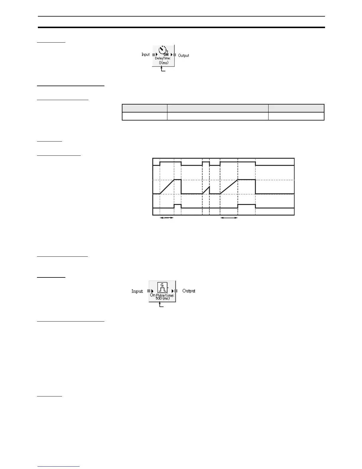
Diagram
General Description The ON-delay Timer function block performs an ON-delay timer operation.
Set Parameters
The delay time must be equal to or greater than the cycle time.
Startup The timer is restarted.
Timing Chart
3-4-3 Pulse Generator
Basic Function The Pulse Generator function block cyclically outputs an ON/OFF pulse on
the Output Enable signal while the Input signal is ON.
Diagram
General Description The Pulse Generator function block cyclically outputs an ON/OFF pulse on
the Output Enable signal while the Input signal is ON.
The pulse’s ON time and OFF time can be set independently between 10 ms
and 3 s, in 10-ms increments. When the ON time is set to 100 ms and the
OFF time is set to 500 ms, the signal will repeatedly be turned ON for 100 ms
and then OFF for 500 ms. The output is always ON at the start of operation.
Note The output pulse width will have an error equivalent to the cycle time. For
example, if the cycle time is 7 ms and the pulse width is set to 100 ms, the
output pulse will be from 98 to 105 ms.
Startup The timer is restarted. When the input signal turns ON, operation starts from
the ON pulse.
The set value is displayed.
Parameter Setting range Default setting
Delay Time 0 ms to 300 s in 10-ms increments 0 ms
Input
Output
Enable
Set value
T imer value
0
IDLE
to RUN
ON-delay time
ON-delay time
The ON pulse width that is set is displayed.

 Loading...


