12
Using this Section Section 3-1
3-1 Using this Section
The following items are described for each function block.
3-2 Specifications for All Function Blocks
Function blocks can be edited according to the application by setting parame-
ters and adding optional inputs, optional outputs, and comments. The tabs
displayed and the settings depend on the function block. This section gives
specifications that are the same for all function blocks.
Item Contents
Instruction Name The name of the function block is given.
Example: Emergency Stop Switch Monitoring
Overview An overview of the function block functions is provided.
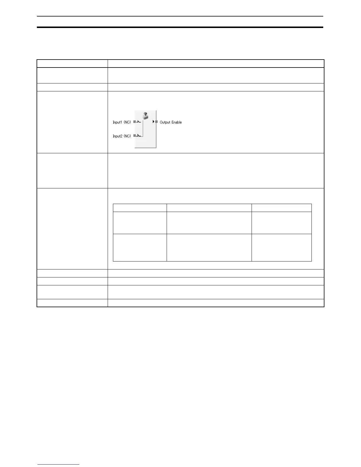
Diagram The Logic Editor symbol is shown.
Example:
General Description The functions of the function block are described in detail.
Example: Emergency Stop Switch Monitoring
When an input from the Emergency Stop Switch is activated, the Output Enable signal is
turned ON. When an input is not activated or when an error is detected in the function block,
the Output Enable signal is turned OFF.
Parameter Settings The parameters to be set for the function block are described.
Example:
Parameter Setting range Default
Input Type • Single Channel
• Dual Channel Equivalent
• Dual Channel Complementary
Dual Channel Equiva-
lent
Discrepancy Time 0 to 30 s in units of 10 ms
Discrepancy time checks are not
performed when this parameter is
set to 0.
30 ms
Optional I/O Settings The additional I/O signals that can be set are described.
Truth Tables The output signals corresponding to combinations of input signals are given.
Error Handling and Error
Resetting
Error status, operations when an error occur, and the recovery procedure are given.
Timing Charts I/O operations are shown in timing charts.

 Loading...


