2
Outline Section 1-1
1-1 Outline
Logic programming for G9SP-series Controllers is performed using function
blocks. Various safety applications can be created by using the function
blocks described in this manual for programming that complies with safety
standards.
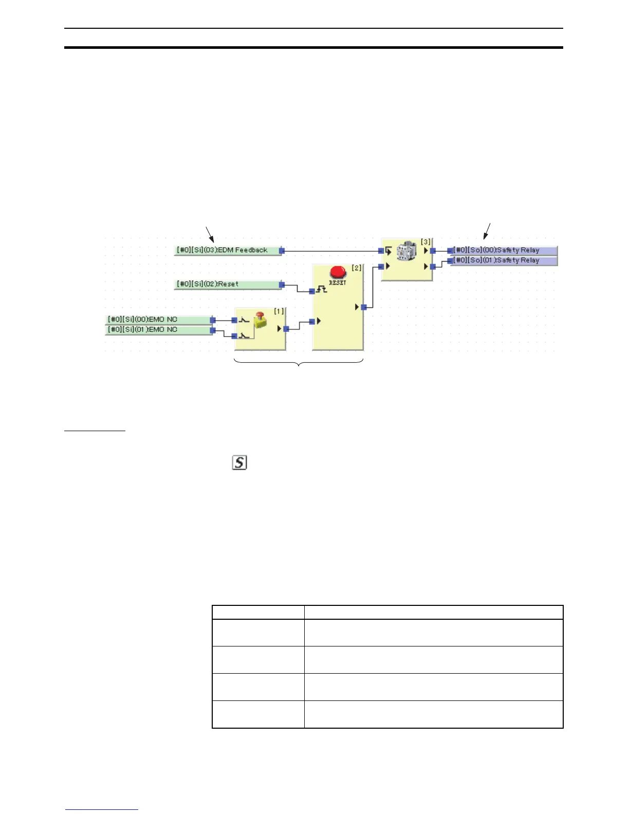
1-1-1 Function Block Basics
Function blocks are created using input tags, which indicate data input
sources, and output tags, which indicate data output destinations. The I/O
tags are connected with connection lines.
1-1-2 I/O Tags
Input Tags
The following data can be used by using input tags.
• Safety Input Terminal Values
The values of the G9SP-series Controller's built-in safety input terminals
can be used. The values that are used, however, are not the terminal val-
ues themselves, but the values after safety input evaluation, such as dual-
channel evaluations or ON/OFF delay judgments.
• Standard Input Terminal Values
The standard input terminal values of an Expansion I/O Unit can be used.
• Status
Status flags can be used to indicate the conditions of the G9SP-series
Controller and whether an error has occurred.
The following status as can be used.
Input tags
Output tags
Function blocks
Status name Meaning
Unit Normal Operat-
ing Flag
0: Error occurred or program stopped.
1: Normal status (no error) and program being executed.
Output Power Supply
Error Flag
0: Output power supply voltage normal.
1: Output power supply voltage error or power supply OFF.
Safety I/O Terminal
Error Flag
0: No error in safety I/O terminals.
1: Error in safety I/O terminals.
Function Block Error
Flag
0: No error in any function block.
1: Error in a function block.

 Loading...


