36
Timer/Counter Function Blocks Section 3-4
Set Parameters
The timer SV must be longer than the G9SP-series Controller's cycle time.
Timing Chart
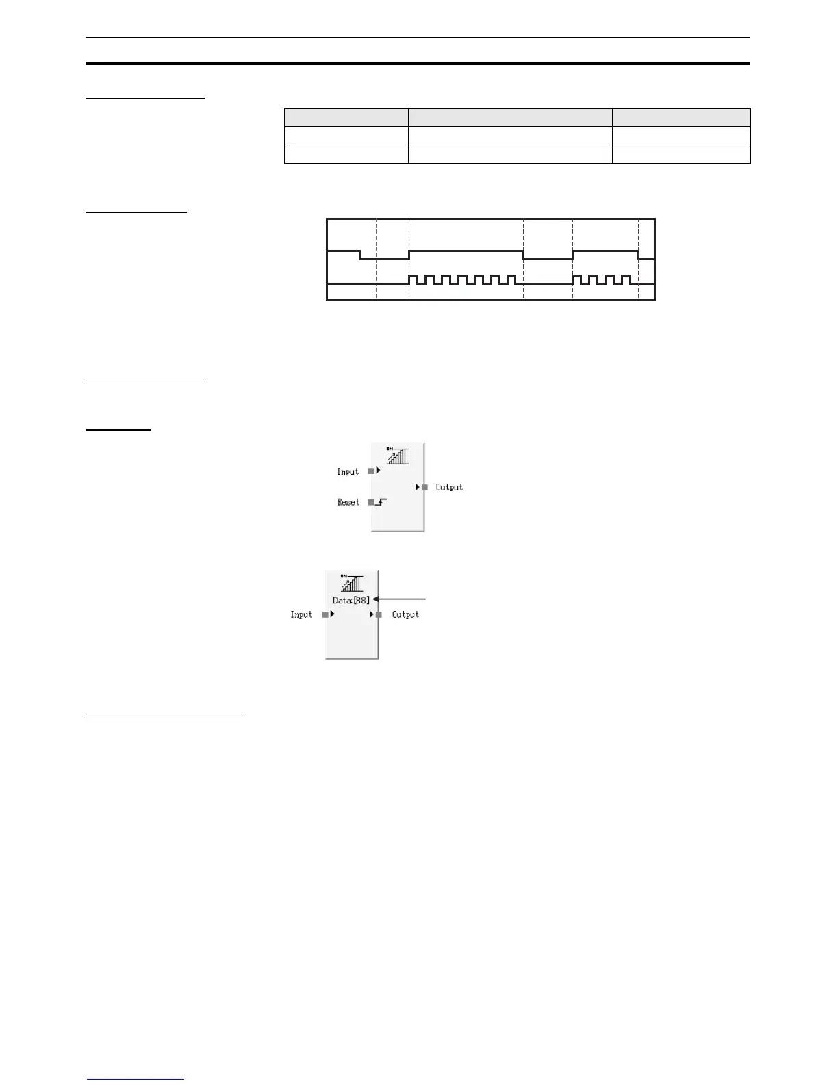
3-4-4 Counter
Basic Function The Counter function block counts the number of input signals and turns ON
the output when the count reaches the specified number.
Diagram
General Description The Counter function block counts the number of input pulses on the Input
signal and turns ON the Output Enable signal when the count reaches the set
value. The function counts the number of OFF-to-ON transitions in the Input
signal.
To detect pulses in the input signal, the Input pulse’s OFF time and ON time
must be longer than the cycle time.
Counting Methods
(Count Type)
The Count Type can be set to Down counter or Up counter (decrementing or
incrementing counter).
With a down (decrementing) counter, the preset SV is the counter’s initial
value and the counter decrements the count by 1 each time a rising edge
(OFF to ON transition) is detected on the Input signal. The Output Enable sig-
nal is turned ON when the count reaches 0.
With an up (incrementing) counter, the counter’s initial value is 0 and the
counter increments the count by 1 each time a rising edge (OFF to ON transi-
tion) is detected on the Input signal. The Output Enable signal is turned ON
when the count reaches the preset SV.
Parameter Setting range Default setting
On Pulse Time 10 ms to 3 s in 10-ms increments 500 ms
Off Pulse Time 10 ms to 3 s in 10-ms increments 500 ms
IDLE to RUN
Input
Output
Enable
Manual Reset (Default)
Auto Reset
The present value
is displayed when
monitoring.
In this example, the
counter present
value is 88.

 Loading...


