56
Safety Device Function Blocks Section 3-5
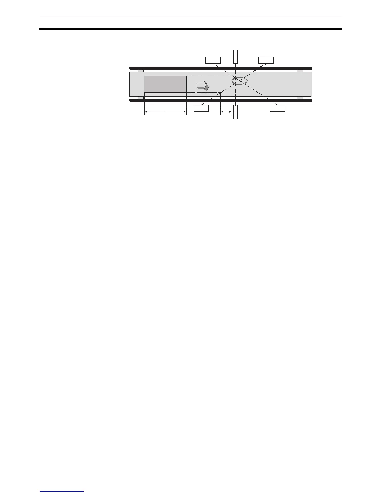
Block Diagram
MS11: Muting sensor connected to Muting Signal 11
MS12: Muting sensor connected to Muting Signal 12
Note The intersection of the two sensors must be after the light curtain.
Muting Sequence
1. In the block diagram above, the light is not interrupted between MS11 and
MS12 and the light curtain, so the Output Enable signal is ON.
2. As the workpiece moves to the right and MS11 and MS12 go ON in order,
muting is enabled.
3. As the workpiece continues advancing, the Output Enable signal is kept
ON even if the Safety Light Curtain is obstructed (i.e., even if the AOPD in-
puts are OFF).
4. As the workpiece continues advancing, the light from MS11 is no longer in-
terrupted by the workpiece, the muting status is cleared and the Muting
Status will go OFF.
Setup Distances
The following formula shows the minimum distance of D1 required for the mut-
ing sensors to provide effective muting function operation:
Formula 1: D1 < L
L: Length of the workpiece
The following formula shows the maximum distance of d1 required for the
muting sensors to provide effective muting function operation:
Formula 2: V × T1min < d1 < V × T1max
V: Transit speed of the workpiece
T1min: G9SP-series Controller cycle time
T1max: Synchronization time setting time
The default setting is 3 s.
D1 must satisfy formula 1 and d1 must satisfy formula 2 in order for the muting
function to be operate effectively. These distance settings must prevent a
passing person from enabling the muting function. Also, the light curtain and
muting sensors must be setup so that a workpiece passes by all of the muting
sensors before the next workpiece arrives at the muting sensors.
MS 11
MS12
L
MS12
1
MS11
Reflected
Board
Reflected
Board
L
Light curtain
Workpiece
D1=
d1
V
 Loading...


