60
Safety Device Function Blocks Section 3-5
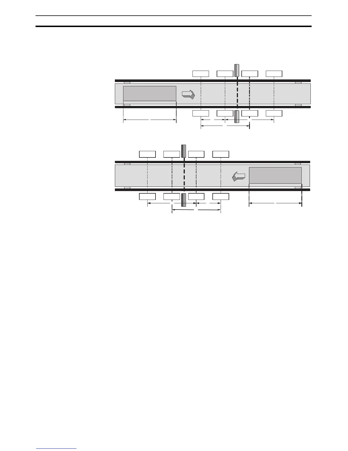
■ Sequential Muting (Both Directions)
Block Diagrams
1. Entrance
2. Exit
MS11: Muting sensor connected to Muting Signal 11
MS12: Muting sensor connected to Muting Signal 12
MS21: Muting sensor connected to Muting Signal 21
MS22: Muting sensor connected to Muting Signal 22
Muting Sequence
1. In the block diagram above, the light is not interrupted between MS11,
MS12, MS21, and MS22 and the Safety Light Current, so the Output En-
able signal is ON.
2. For the entrance, as the workpiece moves to the right and MS11 and MS12
go ON in order (MS22 and MS21 go ON in order at the exit), muting is en-
abled, and the Muting Status goes ON.
3. As the workpiece continues advancing, the Output Enable signal is kept
ON even if the Safety Light Current is obstructed.
4. As the workpiece continues advancing, the workpiece is no longer detect-
ed by MS21 at the entrance (MS12 at the exit), the muting status is
cleared, and the Muting Status goes OFF.
Setup Distances
The setup distance requirements are the same as for Sequential Muting in
Forward Direction.
Light Curtain
L D2
V
L
V
MS22
MS11
MS11
MS12
MS12 MS21
MS22
MS21
Workpiece
D3
D2
d2
Light Curtain
LD2
V
L
V
Workpiece
MS11
MS11
MS12
MS12 MS21
MS22MS21
MS22
D3
D2
d2
 Loading...


