NOTICE: Rapid
deceleration can trigger an overvoltage fault. When faulted, the drive output shuts off, and the motor coasts. To avoid
this uncontrolled motor state and to ensure that the motor stops quickly and safely, set an appropriate Fast-stop time to C1-09.
Setting 20 to 2F: External Fault
By using the External Fault function, the drive can be stopped when problems occur with external devices.
To use the external fault function, set one of the multi-function digital inputs to any value between 20 to 2F. The operator
will display EF where is the number of the terminal (terminal S) to which the external fault signal is assigned.
For example, if an external fault signal is input to terminal S3, “EF3” will be displayed.
Select the value to be set in H1- from a combination of any of the following three conditions:
• Signal input level from peripheral devices (N.O./N.C.)
• External fault detection method
• Operation after external fault detection
The following table shows the relationship between the conditions and the value set to H1-:
Setting
Terminal Status
<1>
Detection Method
<2>
Stopping Method
N.O. N.C.
Always
Detected
Detected
during Run
only
Ramp to Stop
(fault)
Coast to Stop
(fault)
Fast-stop
(fault)
Alarm Only
(continue
running)
20 O O O
21 O O O
22 O O O
23 O O O
24 O O O
25 O O O
26 O O O
27 O O O
28 O O O
29 O O O
2A O O O
2B O O O
2C O O O
2D O O O
2E O O O
2F O O O
<1> Determine the terminal status for each fault, i.e., whether the terminal is normally open or normally closed.
<2>
Determine whether detection for each fault should be enabled only during run or always detected.
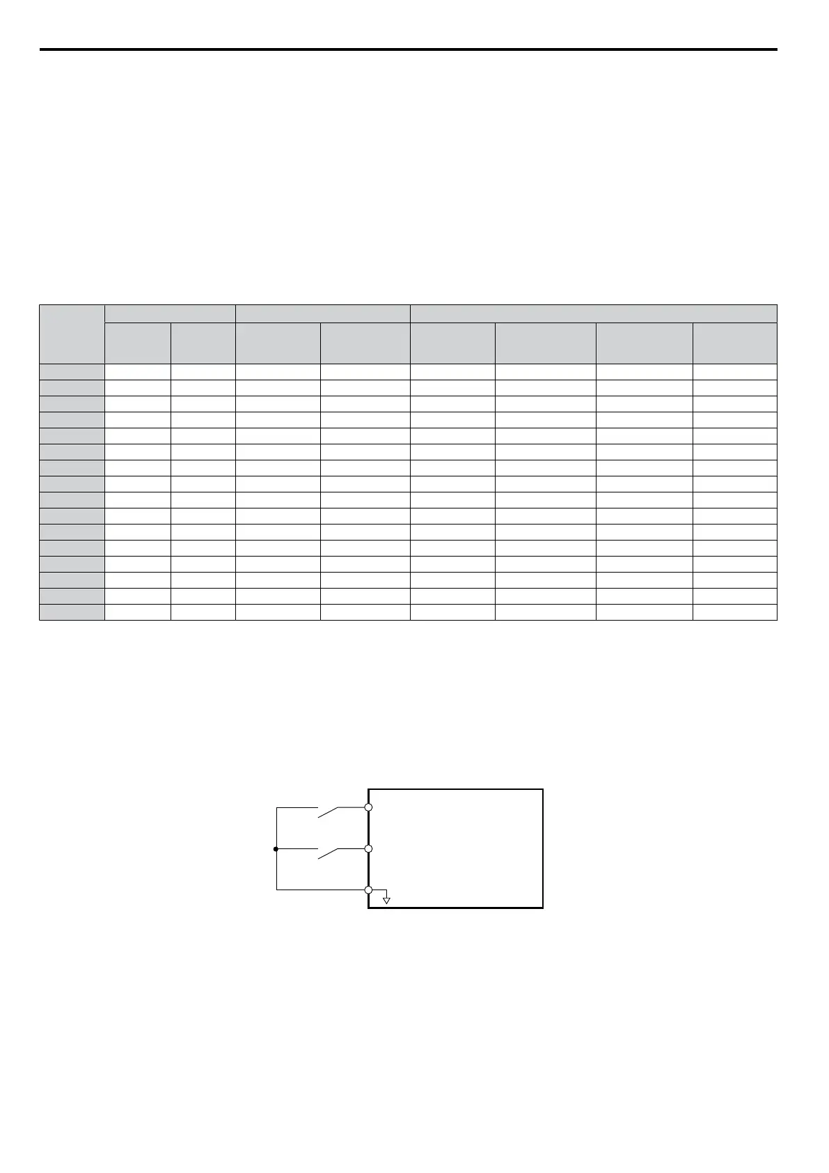
Setting 40/41: Forward Run/Reverse Run Command for 2-Wire Sequence
Sets the drive for 2-Wire sequence.
When the input set to 40 is closed, the drive operates in the forward direction. When the input set for 41 is closed, the drive
will operate in reverse. Closing both inputs at the same time will result in an external fault.
Note: These functions are assigned to the terminals S1 and S2 when the drive is initialized for 2-Wire sequence.
S1
S2
SC
Drive
Forward Run
Reverse Run
Digital Input Common
Figure 5.19 Example Wiring Diagram for 2-Wire Sequence
Setting 61/62: Speed Search 1/2
These
input functions can be used to enable Speed Search. When the Speed Search 1 input (H1- = 61) is enabled the
drive will search the motor speed starting from the maximum output frequency. With Speed Search 2 input (H1- =
62) enabled the Speed Search will be performed starting from the frequency reference.
Note: Operator error oPE03 will result if both Speed Search 1 and Speed Search 2 are set to the input terminals at the same time.
5.6 H: Terminal Functions
94
SIEP C710606 33A OYMC AC Drive – J1000 User Manual