2-7SectionTouch Switches
125
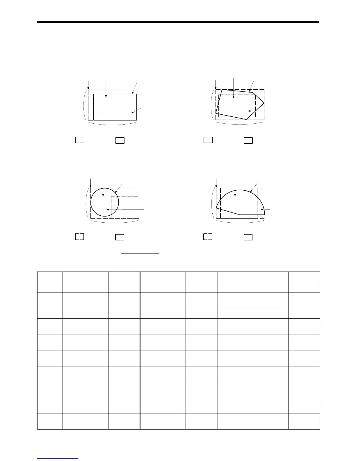
With Free-shape Display Frame
When a free-shape display frame is used, the display graphic can be set any-
where, independently of the area that responds as a touch switch (touch switch
area).
Rectangle Polygon
Position Description
Frame color
Size
(Y direction)
LABEL
OFF color/
ON color
Size (X direction)
Touch
switch area
Display
graphic
Circle Sector
Position Description
Frame color
Size
(Y direction)
LABEL
OFF color/
ON color
Position
Description
Frame color
Size
(Y direction)
OFF color/
ON color
Position Description
Frame color
Size
(Y direction)
OFF color/
ON color
Size (X direction)
Size (X direction) Size (X direction)
Touch
switch area
Display
graphic
LABEL
LABEL
Touch
switch area
Display
graphic
Touch
switch area
Display
graphic
Allocated Bits
Bits can be allocated for lamp bits and interlock bits in the following host (PC)
areas.
Symbol C-series PCs Allocation CV-series PCs Allocation CS/CJ-series PCs Allocation
None IR Area OK CIO Area OK CIO Area OK
H HR Area OK --- --- HR Area
Not for
Host Link
A AR Area OK Auxiliary Area No AR Area OK
L LR Area OK --- --- LR Area
*1
Not for
Host Link
T
TC Area,
Timer PVs
No
Timer Area,
Timer PVs
No
TC Area,
Timer PVs
No
TU --- --- --- ---
TC Area,
Timer Completion Flags
Not for
Host Link
C
TC Area,
Counter PVs
No
Counter Area,
Counter PVs
No
TC Area,
Counter PVs
No
CU --- --- --- ---
TC Area,
Counter Completion Flags
Not for
Host Link
W --- --- --- --- WR Area
Not for
Host Link
TK --- --- --- --- Task Flags
Not for
Host Link