2-14SectionRecipes
234
Number of Digits
The contents of recipe data memory in the PT are all stored as integers. To dis-
play values that contain decimals, set “Decimal” to 1 or more, and specify the
number of digits after the decimal point. Decimal point will be automatically in-
serted.
If the total number of digits is greater than the sum of all the integers and all the
decimals, all digits will be displayed as “*” to denote an error.
An example is given below.
Example: Displaying “123456”
Integer: 8; Decimal: 0
Display reads: 00123456
Integer: 4; Decimal: 4
Display reads: 0012.3456
Integer: 2; Decimal: 4
Display reads: 12.3456
Integer: 1; Decimal: 4
Display reads: *.****
Interlock Function
You can prohibit all recipe touch switch operations depending on the status of
allocated bits (interlock bits) in the PC by setting the interlock function in the rec-
ipe.
The PT will operate as follows, depending on whether the interlock function is
enabled or disabled:
Interlock Function Enabled
The touch switches are enabled only when the interlock bits are ON.
When the interlock bits in the PC are OFF, the following operations are prohib-
ited. At the same time, a buzzer will sound.
• Editing on the PT using the Parameter Editing touch switches.
• Reading/writing words from/to the host using the Read/Write touch switches.
• Scrolling using the scroll touch switches.
• Selecting records using the record selecting touch switches.
Interlock Function Disabled
Recipe touch switch operations are enabled.
Reference: If the touch switch input sound has been turned OFF using the memory switch
settings on the PT, the buzzer will not sound even if a recipe touch switch op-
eration is performed while that operation is prohibited.
If recipe data record editing using a touch switch operation on the PT has been
disabled (i.e., the Lock is ON), you cannot edit recipe data even if the interlock
function is disabled and the touch switch operation is permitted.
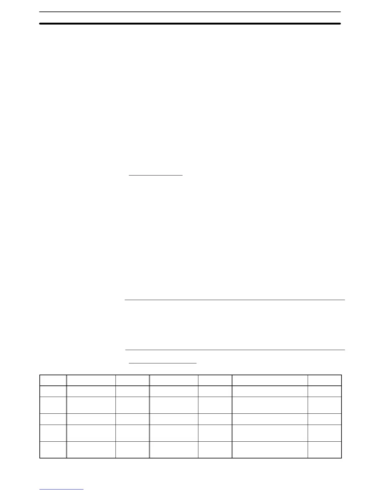
Interlock Bit Allocation
You can allocate interlock bits in the following areas in the PC.
Symbol C-series PCs Allocation CV-series PCs Allocation CS/CJ-series PCs Allocation
None IR Area OK CIO Area OK CIO Area OK
H HR Area OK --- --- HR Area
Not with
Host Link
A AR Area OK Auxiliary Area No AR Area OK
L LR Area OK --- --- LR Area
*1
Not with
Host Link
T
TC Area,
Timer PVs
No
Timer Area,
Timer PVs
No
TC Area,
Timer PVs
No