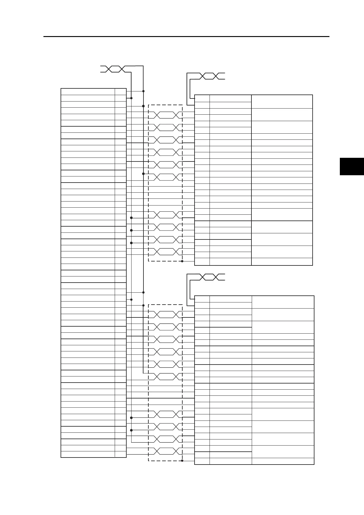
AWG18 twisted pair 1 m
Red: 24 VDC
Black: 24 VDC GND
PCU side
XG4M-5030-T (OMRON)
1
3
5
17
16
19
18
21
20
23
22
15
11
10
12
13
7
6
9
26
27
Servo Drive side (for axis 2 or 4)
10150-3000PE (Sumitomo 3M)
AWG18 twisted pair 1 m
Blue: BKIRCOM
Black: BKIR
AWG18 twisted pair 1 m
Blue: BKIRCOM
Black: BKIR
Servo Drive side (for axis 1 or 3)
10150-3000PE (Sumitomo 3M)
11
10
44
45
46
47
21
22
49
48
23
24
7
30
29
26
31
27
39
38
35
34
37
36
20
13
Shell FG
BKIR
BKIRCOM
+CWLD
−CWLD
+CCWLD
−CCWLD
+A
−A
+B
−B
+Z
−Z
+24VIN
ECRST
RUN
DFSEL
RESET
TLSEL
INP
INPCOM
READY
REDYCOM
/ALM
ALMCOM
SEN
ALMCOM
SEN
SENGND
Encoder phase A+output
Encoder phase A−output
Encoder phase B+output
Encoder phase B−output
Encoder phase Z+output
Encoder phase Z−output
Error counter reset input
Operation command input
Damping filter switching
Alarm reset
Torque limit switching
Frame ground
Brake interlock output
Servo ready completed
output
Alarm output
Positioning completion
output 1
Forward pulse (*1)
(input for line driver only)
Sensor ON input
Reverse pulse (*1)
(input for line driver only)
BKIR
BKIRCOM
+CWLD
−CWLD
+CCWLD
−CCWLD
+A
−A
+B
−B
+Z
−Z
+24VIN
ECRST
RUN
DFSEL
RESET
TLSEL
INP
INPCOM
READY
REDYCOM
/ALM
SENGND
FG
11
10
44
45
46
47
21
22
49
48
23
24
7
30
29
26
31
27
39
38
35
34
37
36
20
13
Shell
25
24
24-V power supply for output
24-V GND for output
Input common
Forward direction pulse output (+)
Forward direction pulse output (−)
Reverse direction pulse output (+)
Reverse direction pulse output (−)
Encoder phase A+
Encoder phase A−
Encoder phase B+
Encoder phase B−
Encoder phase Z+
Encoder phase Z−
Error counter reset output
Error counter reset output
RUN output
General-purpose output
Alarm reset output
Torque limit output
Positioning completed input
General-purpose input
Alarm input
SEN output
Signal ground
24-V power supply for output
24-V GND for output
Input common
Forward direction pulse output (
+
)
Forward direction pulse output (
−
)
Reverse direction pulse output (
+
)
Reverse direction pulse output (
−
)
Encoder phase A+
Encoder phase A−
Encoder phase B+
Encoder phase B−
Encoder phase Z+
Encoder phase Z−
RUN output
General-purpose output
Alarm reset output
Torque limit output
Positioning completed input
General-purpose input
Alarm input
SEN output
Signal ground
2
4
50
39
38
37
36
35
34
33
32
31
30
41
45
44
42
43
49
48
47
29
28
Frame ground
Encoder phase A+output
Encoder phase A−output
Encoder phase B+output
Encoder phase B−output
Encoder phase Z+output
Encoder phase Z−output
Error counter reset input
Operation command input
Damping filter switching
Alarm reset
Torque limit switching
Positioning completion
output 1
Servo ready completed
output
Alarm output
Sensor ON input
Brake interlock output
Reverse pulse (*1)
(input for line driver only)
Forward pulse (*1)
(input for line driver only)
+24-V power supply for controls
+24-V power supply for controls
 Loading...


