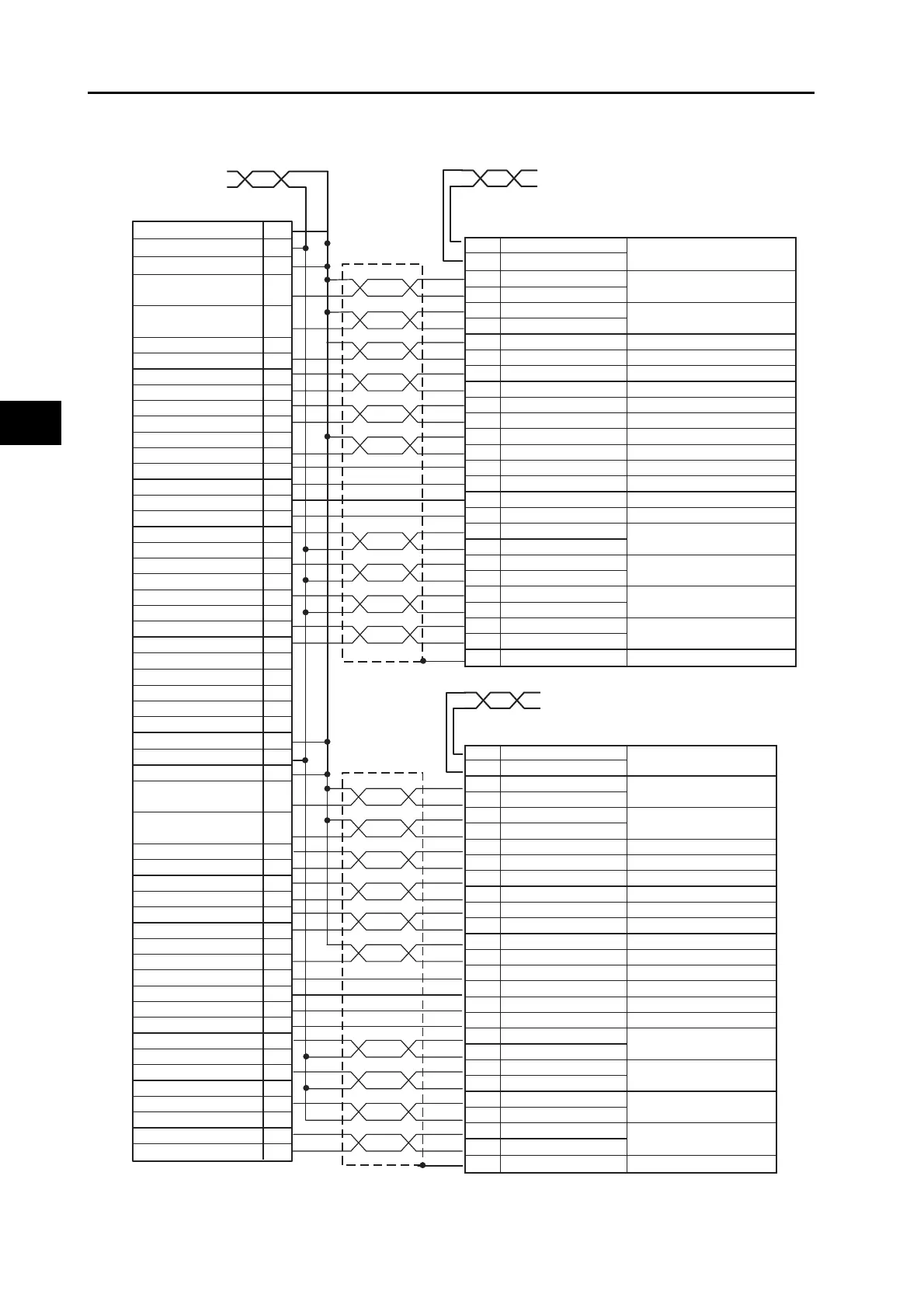
24-V power supply for output
24-V GND for output
Input common
Forward direction pulse output
(with 1.6 kΩ Resistor)
Reverse direction pulse output
(with 1.6 kΩ Resistor)
Encoder phase A+
Encoder phase A−
Encoder phase B+
Encoder phase B−
Encoder phase Z+
Encoder phase Z−
Error counter reset output
RUN output
General-purpose output
Alarm reset output
Torque limit output
Positioning completed input
General-purpose input
Alarm input
SEN output
Signal ground
1
3
5
16
18
21
20
23
22
25
24
15
11
10
12
13
7
6
9
26
27
2
4
50
38
36
35
34
33
32
31
30
41
45
44
42
43
49
48
47
29
28
11 BKIR
10 BKIRCOM
3 +CW/+PULS/+FA
4
−CW/−PULS/−FA
5 +CCW/+SIGN/+FB
6 −CCW/−SIGN/−FB
21 +A
Encoder phase A+output
22 −A
Encoder phase A−output
49 +B
Encoder phase B+output
48 −B
Encoder phase B−output
23 +Z
Encoder phase Z+output
24 −Z
Encoder phase Z−output
7 +24VIN
30
ECRST
Error counter reset input
29 RUN
Operation command input
26 DFSEL
Damping filter switching
31 RESET
Alarm reset
27
TLSEL
Torque limit switching
39 INP
38 INPCOM
35 READY
34 REDYCOM
37 /ALM
36 ALMCOM
20 SEN
13 SENGND
Shell FG
Frame ground
Sensor ON input
Reverse pulses, feed pulses,
or phase A (*1)
Brake interlock output
Servo ready completed
output
Alarm output
Positioning completion
output 1
Forward pulse, direction signal,
or phase B (*1)
Servo Drive side (for axis 2 or 4)
10150-3000PE (Sumitomo 3M)
11
BKIR
10
BKIRCOM
3
+CW/+PULS/+FA
4
−CW/−PULS/−FA
5
+CCW/+SIGN/+FB
6
−CCW/−SIGN/−FB
21
+A Encoder phase A+output
22
−A Encoder phase A−output
49
+B Encoder phase B+output
48
−B Encoder phase B−output
23
+Z Encoder phase Z+output
24
−Z Encoder phase Z−output
7
+24VIN
30
ECRST Error counter reset input
29
RUN
Operation command input
26
DFSEL Damping filter switching
31
RESET Alarm reset
27
TLSEL Torque limit switching
39
INP
Positioning completion
output 1
38
INPCOM
35
READY
Servo ready completed
output
34
REDYCOM
37
/ALM
Alarm output
36
ALMCOM
20
SEN
Sensor ON input
13 SENGND
Shell FG Frame ground
Reverse pulses, feed
pulses, or phase A (*1)
Forward pulse, direction
signal, or phase B (*1)
Brake interlock output
AWG18 twisted pair 1 m
Blue: BKIRCOM
Black: BKIR
Red: 24 VDC
Blue: BKIRCOM
Black: 24 VDC GND
Black: BKIR
PCU side
XG4M-5030-T (OMRON)
AWG18 twisted pair 1 mAWG18 twisted pair 1 m
Servo Drive side (for axis 1 or 3)
10150-3000PE (Sumitomo 3M)
+24-V power supply for controls
+24-V power supply for controls
+
 Loading...


