8-34
8-4 Analog Control Parameters
OMNUC G5-SERIES AC SERVOMOTOR AND SERVO DRIVE USER'S MANUAL
8
Parameter Details
Set the relation between the voltage applied to the torque reference input (TREF1: CN1 pin 14,
TREF2: CN2 pin 16) and the motor speed.
Refer to "5-3 Torque Control" (P.5-14) for more information on torque command scale.
Explanation of Set Values
Reverse the polarity of the torque command input (REF/TREF1: CN1 pin 14 or PCL/TREF2: CN1
pin 16).
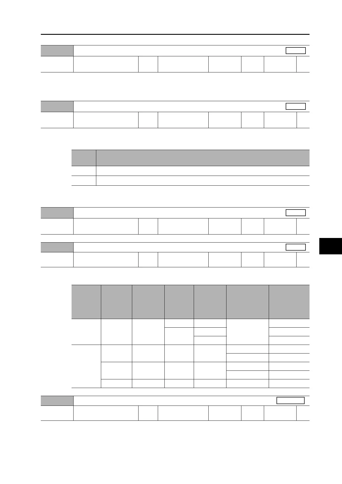
Corresponding speed limit values during torque control is shown in the table below.
Pn319
Torque Command Scale
Setting
range
10 to 100 Unit 0.1 V/100%
Default
setting
30
Power OFF
and ON
−
Pn320
Analog Torque Command Rotation Direction Switching
Setting
range
0 to 1 Unit −
Default
setting
0
Power OFF
and ON
−
Torque
Set
value
Description
0
Direction of motor torque: The +command indicates the forward direction as viewed from the shaft end.
1
Direction of motor torque: The +command indicates the reverse direction as viewed from the shaft end.
Pn321
Speed Limit Value Setting
Setting
range
0 to 20,000 Unit r/min
Default
setting
0
Power OFF
and ON
−
Pn322
Reverse Direction Speed Limit Value Setting
Setting
range
0 to 20,000 Unit r/min
Default
setting
0
Power OFF
and ON
−
Torque
Command/
Speed Limit
Selection
(Pn317)
Speed
Limit
Value
Setting
(Pn321)
Reverse
Direction
Speed Limit
Value Setting
(Pn322)
Zero Speed
Designation
Selection
(Pn315)
Zero speed
clamp
Analog torque
command
direction
Speed limit
value
0 0 to 20,000 Not affected
0 Not affected
Not affected
Pn321 set value
1 to 3
OFF
Pn321 set value
ON 0
2
0 to 20,000 0 to 20,000 0 Not affected
Forward direction Pn321 set value
Reverse direction
Pn322 set value
0 to 20,000 1 to 20,000 1 to 3 OFF
Forward direction Pn321 set value
Reverse direction
Pn322 set value
0 to 20,000 1 to 20,000 1 to 3 ON Not affected 0
Pn323
External Feedback Pulse Type Selection
Setting
range
0 to 2 Unit −
Default
setting
0
Power OFF
and ON
Yes
 Loading...


