Standards Compliance
5
5.3 UL Standards
SIEPYEUOQ2A01A AC Drive Q2A Technical Manual 197
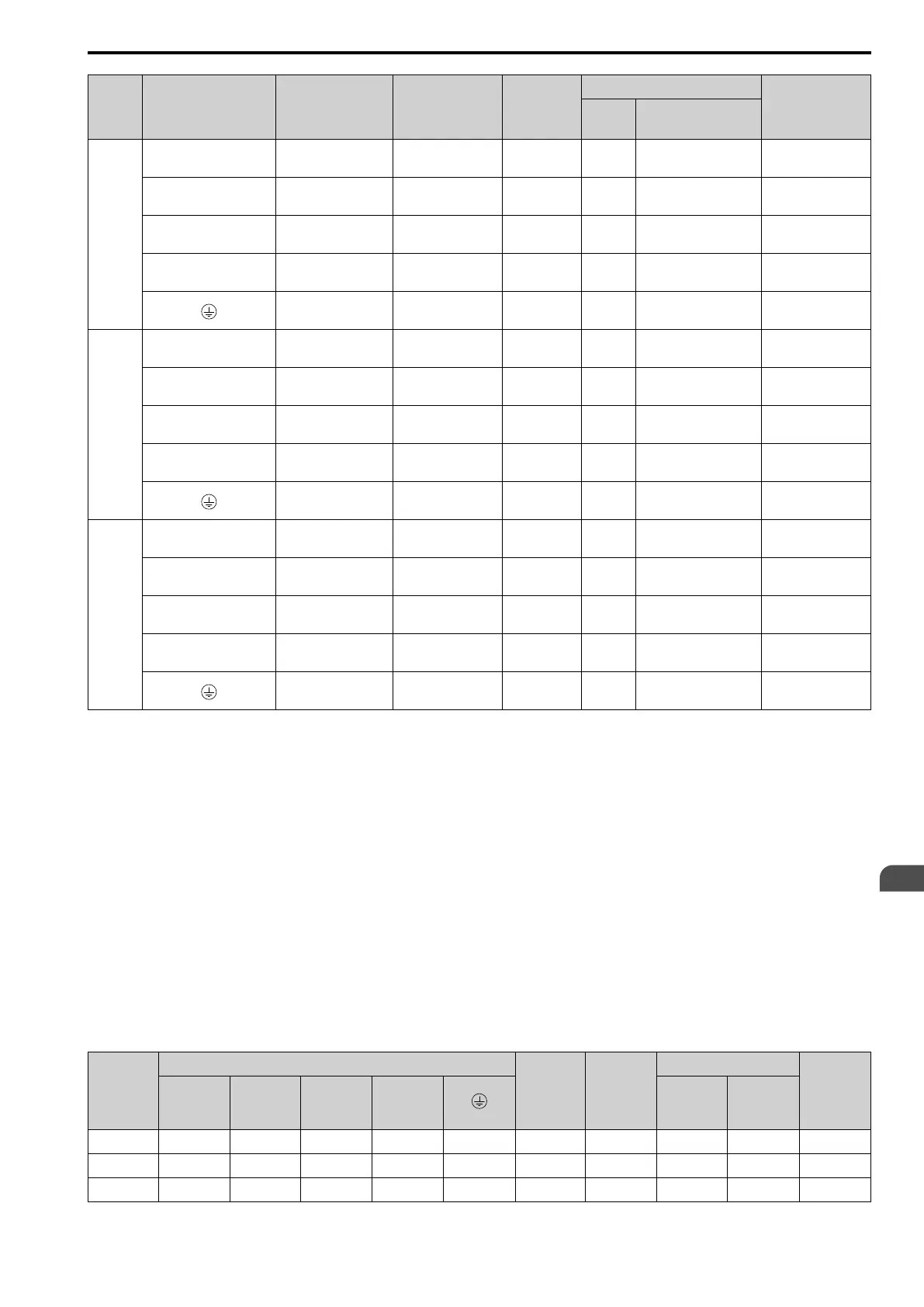
Model Terminals
Recommended
Gauge
AWG, kcmil
Applicable Gauge
(IP20 Applicable
Gauge
*1
)
AWG, kcmil
Wire
Stripping
Length
*2
mm
Terminal Screw
Tightening Torque
N∙m (lb∙in.)
Size Shape
4453
R/L1, S/L2, T/L3, R1/L11,
S1/L21, T1/L31
250 × 4P
2/0 - 300 × 4P
(250 - 300 × 4P)
- M12 Hex self-locking nut
35
(310)
U/T1, V/T2, W/T3 4/0 × 4P
2/0 - 300 × 4P
(250 - 300 × 4P)
- M12 Hex self-locking nut
35
(310)
-, +1 4/0 × 4P
3/0 - 400 × 4P
(300 - 400 × 4P)
- M12 Hex self-locking nut
35
(310)
+3 3/0 × 4P
2 - 4/0
(4/0 × 4P)
- M12 Hex self-locking nut
35
(310)
1/0
1/0 - 300
(-)
- M12 Hex bolt (slotted)
32 - 40
(283 - 354)
4568
R/L1, S/L2, T/L3, R1/L11,
S1/L21, T1/L31
250 × 4P
2/0 - 300 × 4P
(250 - 300 × 4P)
- M12 Hex self-locking nut
35
(310)
U/T1, V/T2, W/T3 4/0 × 4P
2/0 - 300 × 4P
(250 - 300 × 4P)
- M12 Hex self-locking nut
35
(310)
-, +1 300 × 4P
3/0 - 400 × 4P
(300 - 400 × 4P)
- M12 Hex self-locking nut
35
(310)
+3 3/0 × 4P
2 - 4/0 × 4P
(4/0 × 4P)
- M12 Hex self-locking nut
35
(310)
2/0
2/0 - 300
(-)
- M12 Hex bolt (slotted)
32 - 40
(283 - 354)
4675
R/L1, S/L2, T/L3, R1/L11,
S1/L21, T1/L31
300 × 4P
2/0 - 300 × 4P
(250 - 300 × 4P)
- M12 Hex self-locking nut
35
(310)
U/T1, V/T2, W/T3 300 × 4P
2/0 - 300 × 4P
(250 - 300 × 4P)
- M12 Hex self-locking nut
35
(310)
-, +1 400 × 4P
3/0 - 400 × 4P
(300 - 400 × 4P)
- M12 Hex self-locking nut
35
(310)
+3 4/0 × 4P
2 - 4/0 × 4P
(4/0 × 4P)
- M12 Hex self-locking nut
35
(310)
2/0
2/0 - 300
(-)
- M12 Hex bolt (slotted)
32 - 40
(283 - 354)
*1 For IP20 protection, use wires that are in the range of applicable gauges.
*2 Remove insulation from the ends of wires to expose the length of wire shown.
*3 For wire gauges more than AWG 8, tighten to a tightening torque of 4.1 N∙m to 4.5 N∙m (36 lb∙in. to 40 lb∙in.).
*4 Terminals - and +1 have two screws. The Recommended Gauge is the wire gauge for one terminal.
*5 A junction terminal is necessary to connect a braking resistor unit (LKEB-series) to terminals B1 and B2.
■ Closed-Loop Crimp Terminals
To comply with UL standards on drive models 4208 to 4675, use UL-approved closed-loop crimp terminals. Use
the tools recommend by the terminal manufacturer to crimp the closed-loop crimp terminal. The manufacturer
recommends closed-loop crimp terminals from JST Mfg. Co., Ltd. and insulation caps from Tokyo DIP Co., Ltd.
Comply with local standards for correct wire gauges in the region where the drive is used.
Contact the manufacturer or your nearest sales representative to order.
Refer to Table 5.8 to select crimp terminals as specified by drive model and wire gauge.
Note:
To comply with UL standards, use only insulated crimp terminals or crimp terminals with insulation tubing. Use UL-Listed, vinyl-
coated insulated copper wires for operation with a continuous maximum permitted temperature of 75 °C at 600 V.
Table 5.8 Closed-Loop Crimp Terminals and Insulation Caps for 400 V Class
Model
Recommended Gauge (AWG, kcmil)
Terminal
Screw Size
Crimp
Terminal
Model
Crimping Tool
Insulation
Cap Model
R/L1
S/L2
T/L3
U/T1
V/T2
W/T3
-, +1 +3 Tool Model Die Jaw
4002, 4004 - - - - 12 M4 R5.5-4 YA-4 AD-900 TP-005
4005 - 4012 - - - - 10 M4 R5.5-4 YA-4 AD-900 TP-005
4018, 4023 - - - - 10 M5 R5.5-5 YA-4 AD-900 TP-005

 Loading...


