12.2 b: APPLICATION
540 SIEPYEUOQ2A01A AC Drive Q2A Technical Manual
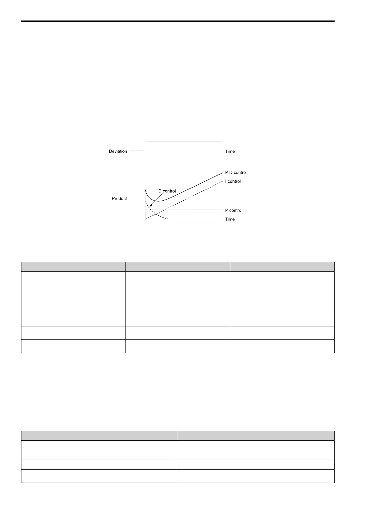
• I control
I control is the integral of the deviation. It uses an integral value of the deviation to output the product (the
controlled output). I control helps align the feedback value and the target value.
• D control
D control is the derivative of the deviation. D control has an effect on drive output when there are sudden, large
changes in the output. It quickly returns drive output to the value before the sudden change. It multiplies a time
constant by a derivative value of the deviation (slope of the deviation), and adds that result to PID input to
calculate the deviation of the signal, then it corrects the deviation.
Note:
D control has causes less stable operation because the noise changes the deviation signal. Use D control only when necessary.
■ PID Control Operation
The modified output (output frequency) changes when the drive uses PID control to keep the deviation (the
difference between the target value and the feedback value) constant.
Figure 12.28 PID Control Operation
■ PID Control Applications
Table 12.9 PID Control Applications
Application Description Sensors Used
Speed control • The drive uses a feedback signal for the machine
speed, and adjusts that speed to align with the target
value.
• The drive uses speed data from other machinery as the
target value to do synchronous control. The drive then
adds that target value to the feedback from the
machine it is operating to align its speed with the other
machinery.
Tacho generator
Pressure control The drive uses feedback from the actual pressure to hold
constant pressure.
Pressure sensor
Flow control The drive uses feedback from the actual flow to hold
constant flow.
Flow rate sensor
Temperature control The drive uses feedback from the actual temperature to
control a fan and hold constant temperature.
Thermocoupler, thermistor
■ Input Methods for the PID Setpoint
Use b5-01 = 1 [PID Enable = Enabled] and b5-70 to b5-72 to select how the PID setpoint is input to the drive.
When b5-70 = 0 [PID MainRefMode = PID only] or b5-70 = 1 [Fref + PID] and b5-72 = 0 [PID D-FF Mode =
D=Fdback], the frequency reference set in b1-01 [Freq. Ref. Sel. 1] or b1-15 [Freq. Ref. Sel. 2] will be the PID
setpoint, or the one of the values shown in Table 12.10 will be the PID setpoint.
When b5-70 = 1 [PID MainRefMode = Fref + PID] or b5-70 = 1 [Fref + PID] and b5-72 = 0 [PID D-FF Mode
= D=Fdback], one of the inputs in Table 12.10 will be the PID setpoint.
Table 12.10 Input Methods for the PID Setpoint
Input Methods for the PID Setpoint Setting
Multi-function analog input terminal AI1 Set H3-02 = 10 [AI1 Function Selection = PID SetPoint].
Multi-function analog input terminal AI2 Set H3-10 [AI2 Function Selection] = 10 .
Multi-function analog input terminal AI3 Set H3-06 [AI3 Function Selection] = 10.
Modbus register 0006H Sets Modbus register 000FH (Control Selection Setting) bit 1 to 1 (PID setpoint input).
Enters the PID setpoint to Modbus register 0006H (PID Target, 0.01% units, signed).

 Loading...


