12.6 F: OPTIONS
650 SIEPYEUOQ2A01A AC Drive Q2A Technical Manual
■ F6-16 Gateway Mode
No.
(Hex.)
Name Description
Default
(Range)
F6-16
(0B8A)
Gateway Mode
Sets the gateway mode operation and the number of connected slave drives.
0
(0 - 4)
0 : Disabled
1 : 1 Slave Drive
2 : 2 Slave Drives
3 : 3 Slave Drives
4 : 4 Slave Drives
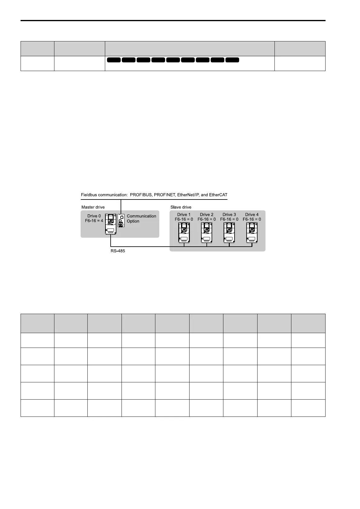
Gateway Mode processes communications through internal the RS-485 communication function to relay data
from a drive that has the communication option to more than one drive that does not have the communication
option. This function lets you use fieldbus communication to connect a maximum of 5 drives with only one
communication option. The drive sends these commands and responses between the controller (Host device),
master drive (Drive 0), and the slave drives (Drive 1 to Drive 4).
• Commands: Run command and frequency reference
• Output frequency and drive status (during run, faults)
• Read and write parameters
• Read monitors
NOTICE: When you use Gateway Mode, do not install the communication option in slave drives. Failure to obey can cause
problems with synchronization of drive commands and responses.
Note:
• Response speed with the communication option is slower than with point-to-point communications.
• Set H5-03 [Communication Parity Selection] to the same value on the master drive and slave drives.
Table 12.36 shows the parameter settings when you connect 4 slave drives:
Table 12.36 Parameter Settings to Connect 4 Slave Drives
F6-16
[Gateway
Mode]
H5-01
[Mbus
Address]
H5-02
[Mbus
BaudRate]
H5-03
[Mbus Parity]
H5-06
[Mbus Tx Wait
Time]
H5-09
[Mbus CE
Detect Time]
b1-01
[Freq. Ref. Sel.
1]
b1-02
[Run Comm.
Sel 1]
Drive0
(Master Drive)
1 - 4 1F (Default)
*2 *2
5 ms
*3
2.0 s minimum
*4
3 [Option PCB] 3 [Option PCB]
Drive1
(Slave Drive 1)
0 01
*2 *2
5 ms
*3
0.9 s minimum
*4
2 [Modbus
Communications]
*5
2 [Modbus
Communications]
*5
Drive2
(Slave Drive 2)
0 02
*2 *2
5 ms
*3
0.9 s minimum
*4
2 [Modbus
Communications]
*5
2 [Modbus
Communications]
*5
Drive3
(Slave Drive 3)
0 03
*2 *2
5 ms
*3
0.9 s minimum
*4
2 [Modbus
Communications]
*5
2 [Modbus
Communications]
*5
Drive4
(Slave Drive 4)
0 04
*2 *2
5 ms
*3
0.9 s minimum
*4
2 [Modbus
Communications]
*5
2 [Modbus
Communications]
*5
*1 Set the number of connected slave drives.
*2 Make sure that you set the communications speed and communications parity to the same value on the master drive and slave drives.
*3 To correctly detect the response timeout, do not change the value of H5-06 from the default value.
*4 Set H5-09 ≥ 0.9 s. When H5-09 < 0.9, the drive will detect CE before it detects a response timeout.
*5 Set the Run command and frequency reference source on slave drives to Modbus communications.

 Loading...


