5-18
CHAPTER 5 Periodic Inspection
2. Y-axis
1) Prepare the following tools and items.
• Harmonic grease 4B No.2
• Waste cloth (rag)
• Phillips-head screwdriver
• Hex wrench set
• Screw Lock (thread sealant)
• Torque-limiting wrench
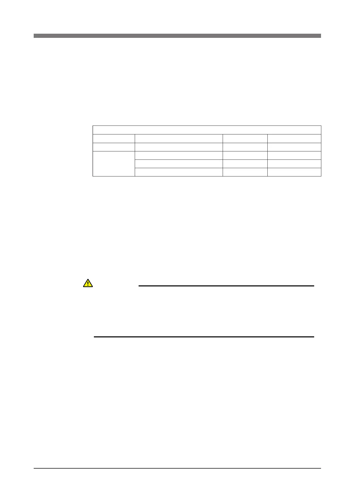
• Replacement parts (See table below.)
Replacement parts
Parts name Type No .
OMRON Parts No.
Note
Harmonic drive SHF-17-50 KN3-M2510-002
S63(JIS) KN3-M2519-000
Lower part of harmonic drive
O-ring
Cross section diameter: 1.00mm x Inner diameter: 29.50mm
KN3-M257K-000 For motor
Cross section diameter: 0.80mm x Inner diameter: 45.40mm
KN3-M257L-000
Supplied with harmonic drive
2) Turn off the controller.
3) Place a sign indicating that the robot is being inspected, to keep others from
operating the controller switch.
4) Enter the safeguard enclosure.
5) Remove the Y-axis arm upper cover. Place the cover on the robot base
(pedestal) side with the machine harness still connected.
Refer to "7 Removing the Robot Covers" in Chapter 4 for removing the
covers.
WARNING
WHEN YOU REMOVE THE Y-AXIS ARM INSTALLATION BOLTS (M3×20L,
8 PIECES) IN THE NEXT STEP, THE Y-AXIS ARM MAY COME OFF
CAUSING A HAZARDOUS SITUATION. BE ESPECIALLY CAREFUL TO
KEEP THE ARM FROM FALLING WHEN A HEAVY TOOL IS ATTACHED
TO THE ARM TIP.
 Loading...


