3-33
CHAPTER 3 Installation
6-4 Attaching the end effector
The manipulator part to which an end effector is attached must have adequate
strength and rigidity, as well as gripping force to prevent positioning errors. Ta-
ble 3-1 shows the maximum load that can be applied to the end effector attach-
ment of each robot model. Recommended methods for attaching end effectors
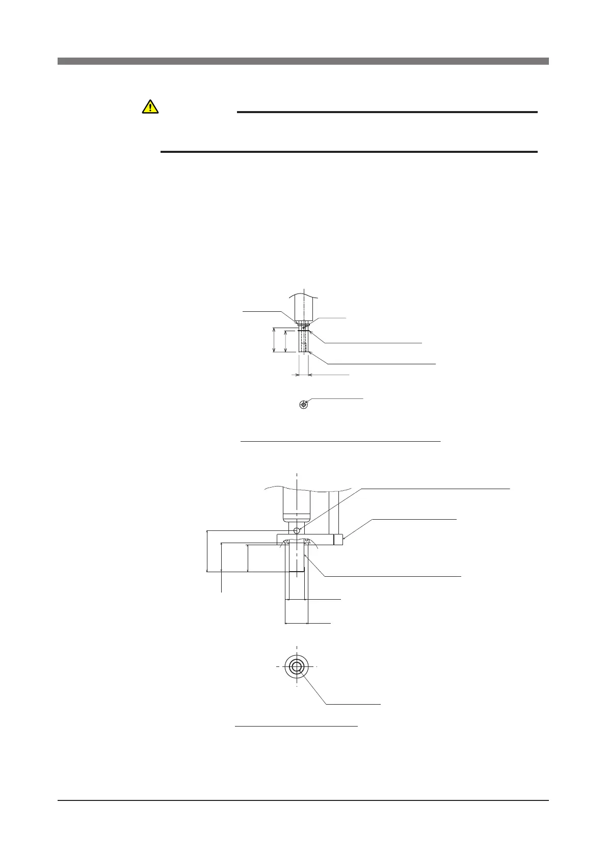
are shown in Table 3-2 and Fig. 3-41. Refer to Fig. 3-39 for details on the end
effector attachment of each robot model.
When checking end effector operation, refer to "6 Trial Operation" in Chapter 1.
Fig. 3-39 (1)
M16´2 depth25
Support shaft clamp plate
25
-0.01
-0.02
39
69
45
47.8
R6YXX1200: Z-axis tip shape
∅10
+0.2
0
Spline shaft (hollow): hollow diameter ∅12
(Hole for attaching user tool or
R-axis rotation during direct teaching)
∅
∅
Fig. 3-39 (2)
R6YXH250, R6YXH350, R6YXH400: Z-axis tip shape
41
36
3
0
+0.2
16h7
-0.018
0
Z-axis mechanical
stopper
(Hole for attaching user tool or
R-axis rotation during direct teaching)
Retaining ring to set the user tool
(See cautions on page 3-55.)
Spline shaft (hollow): hollow diameter 7
M8×1.25, depth 15
∅
∅
∅
WARNING
BEFORE ATTACHING THE END EFFECTOR, BE SURE TO TURN OFF THE
CONTROLLER.
 Loading...


