3-3
CHAPTER 3 Installation
1-2 Installation base
1) Prepare a sufciently rigid and stable installation base, taking account of
the robot weight including the end effector (gripper), workpiece and reac-
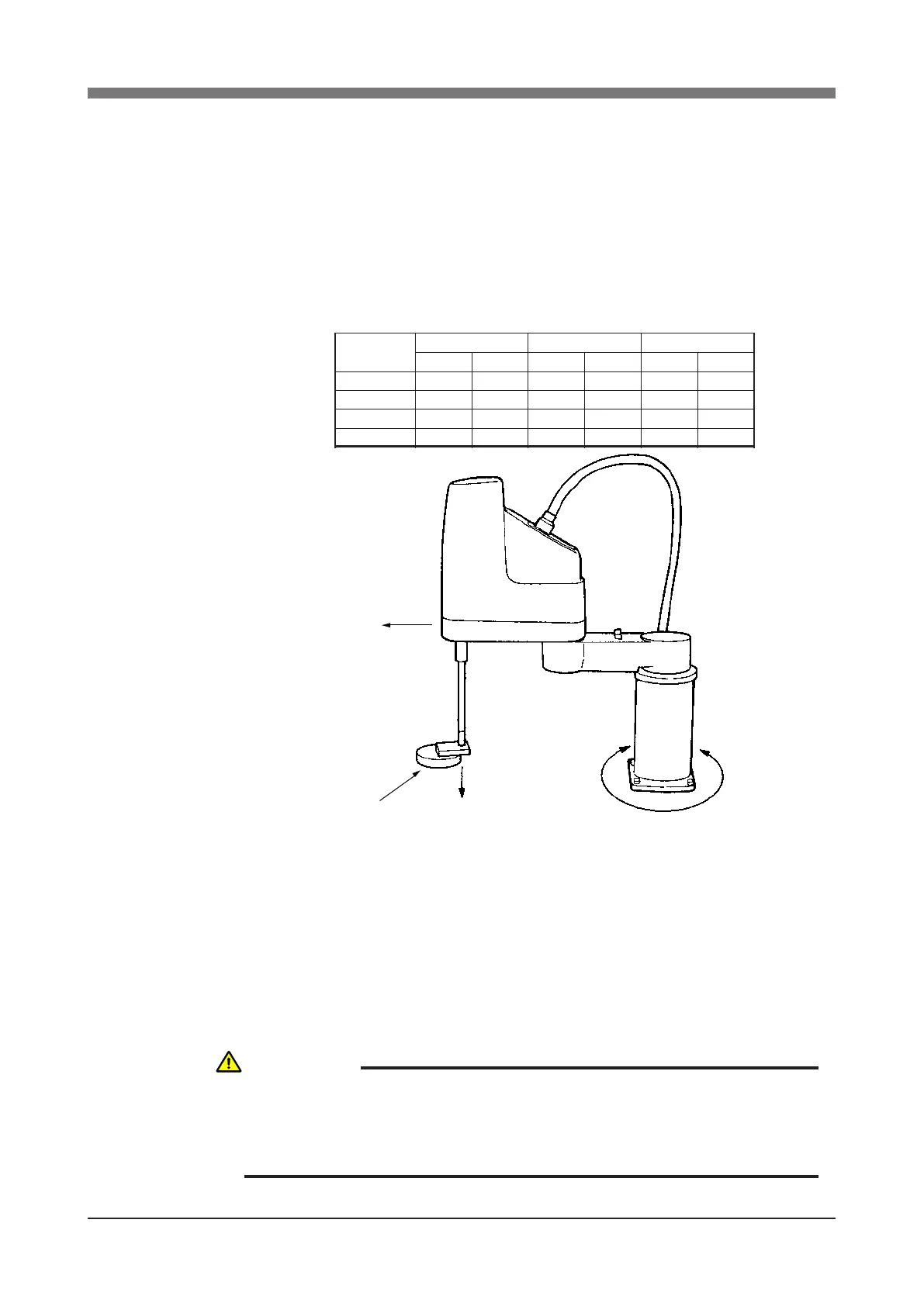
tion force while the robot is operating. The maximum reaction force (see
Fig. 3-1) applied to the X-axis and Z-axis of each robot during operation is
shown in the table below. These values are an instantaneous force applied
to the robot during operation and do not indicate the maximum load capac-
ity.
The maximum reaction force
Robot Model
R6YXH250
R6YXH350
R6YXH400
N kgf Nm kgfm N kgf
305 31 56 6 40 4
330 34 56 6 40 4
391 40 56 6 40 4
336
1029 105 108
F
X
max M
X
max F
Z
max
R6YXX1200
3293
11
Fig. 3-1 Maximum reaction force applied during operation
2) The parallelism of the installation base surface must be machined within a
precision of ±0.05mm/500mm. The robot base mount must be installed fac-
ing down and in a level position.
3) Tap holes into the surface of the installation base. For machining dimen-
sions and positions, refer to "1-2 External view and dimensions" in Chapter
7.
4) Securely x the installation base on the oor with anchor bolts.
WARNING
DO NOT PLACE THE ROBOT ON A MOVING INSTALLATION BASE.
EXCESSIVE LOADS WILL BE APPLIED TO THE ROBOT ARM BY
MOVEMENT OF THE INSTALLATION BASE, RESULTING IN DAMAGE
TO THE ROBOT.
 Loading...


