3-16
CHAPTER 3 Installation
5 User Wiring and User Tubing
1) The X series robots are equipped with user wires and air tubes in the ma-
chine harness. The table below shows the number of wires and air tubes
available for each robot model.
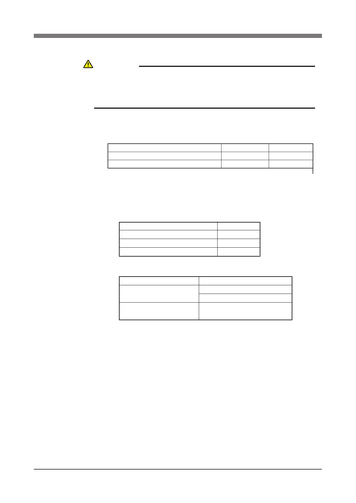
Robot model
R6YXH250, R6YXH350, R6YXH400
R6YXX1200
User wiring
10wires
20wires
User tubing
4, 3tubes
6, 3tubes
∅
∅
(Robot models for custom specications may have different wiring or tub-
ing.)
The specications of the user wires and air tubes are shown below. Always
observe the specications.
30V
1.5A
0.2mm
2
Yes
User Wiring
Rated voltage
Allowable current
Nominal cross-section area of conductor
Shield
User Tubing
Maximum pressure
Outer diameter × inner diameter
Fluid
0.58MPa (6Kgf/cm
2
)
φ4mm×φ2.5mm
φ6mm×φ4mm
Dry clean air not containing deteriorated
compressor oil; filtration 40µm or less
2) A D-sub connector for user wiring and a bulkhead union for user tubing are
provided one each on the arm side and pedestal side. For the locations, re-
fer to "1-2 External view and dimensions" in Chapter 7.
WARNING
ALWAYS TURN OFF THE CONTROLLER AND SHUT OFF AIR SUPPLY
BEFORE ATTEMPTING WIRING AND PIPING WORK. IF AIR OR POWER
IS SUPPLIED DURING THIS WORK, THE MANIPULATOR MAY MOVE
ERRONEOUSLY CAUSING A HAZARDOUS SITUATION.
 Loading...


