3-17
CHAPTER 3 Installation
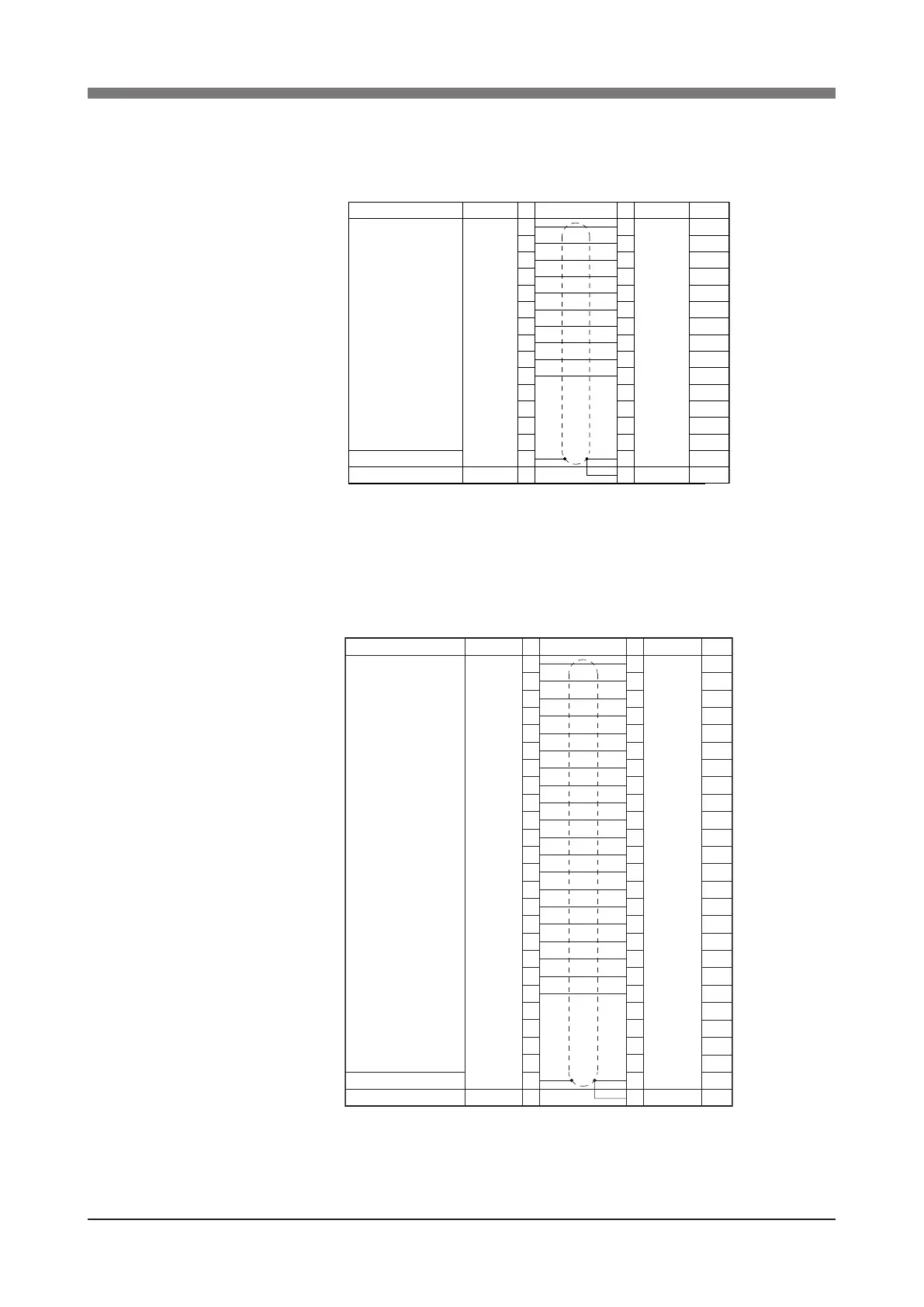
3) Signal wiring connections in the machine harness
1. R6YXH250, R6YXH350, R6YXH400
Connector pins 1 to 10 can be used. Pin 15 is connected to a shield wire
and cannot be used as a signal wire.
Connector
I O
(Arm side)
NO
1
2
3
4
5
6
7
8
9
10
11
12
13
14
15
Signal
User signal line
Shield
Flame ground
Connection NO
1
2
3
4
5
6
7
8
9
10
11
12
13
14
15
1
Connector
I O
(Base side)
FG
Color
Brown
Red
Orange
Blue
Violet
Grey
White
Black
Brown
Red
Orange
Blue
Violet
Grey
Green
Green
(Robots models with non-standard specications
may have different wiring colors.)
2. R6YXX1200
Connector pins 1 to 20 can be used. Pin 25 is connected to a shield wire
and cannot be used as a signal wire.
NO
1
2
3
4
5
6
7
8
9
10
11
12
13
14
15
16
17
18
19
20
21
22
23
24
25
Signal
User signal line
Shield
Flame Ground
NO
1
2
3
4
5
6
7
8
9
10
11
12
13
14
15
16
17
18
19
20
21
22
23
24
25
1
Connector
I O
(Arm side)
Connection
Connector
I O
(Base side)
FG
Color
Brown
Red
Orange
Blue
Violet
Grey
White
Black
Brown
Red
Orange
Blue
Violet
Grey
White
Black
Brown
Red
Orange
Blue
Green
Green
(Robots models with non-standard specications
may have different wiring colors.)
 Loading...


