16
Component Names and Functions Section 2-1
2-1 Component Names and Functions
Component Names
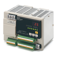
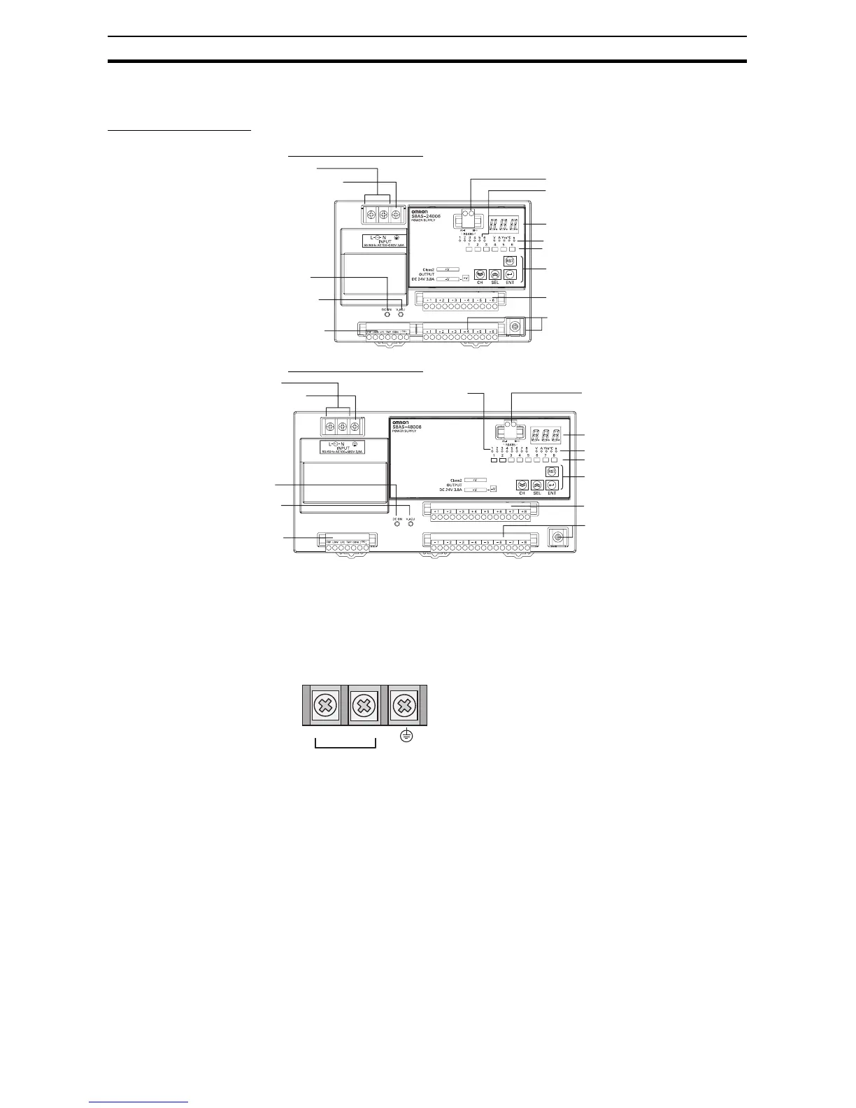
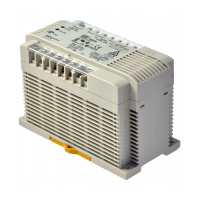
■ 240-W Output Models
■ 480-W Output Models
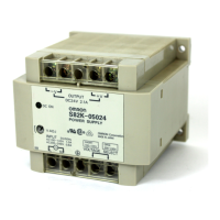
(1) AC Input Terminals (L and N) and (2) Protective Earth (PE) Terminal
Connect the input power supply (100 to 240 VAC, 50/60 Hz) (commercial
power) to the Power Supply.
Do not connect an inverter output as the power supply.
Make sure that the protective earth (PE) terminal is connected to ground to
prevent electric shock or malfunction.
(3) Positive (+) and (4) Negative (−) Branch Output Terminals
Connect to each branch output. Positive and negative branch outputs are con-
nected to separate terminal blocks with two positive and two negative termi-
nals for each branch output.
1. AC input terminals
2. Protective earth (PE) terminal
3. Branch output terminals (+)
4. Branch output terminals (−)
6. Output indicator (DC ON)
7. Output voltage adjuster (V.ADJ)
8. Seven-segment display
5. I/O signal terminals
13. Communications terminal
9. Branch output indicators
10. Unit indicators
11. Status indicators
12. Operation keys
1. AC input terminals
2. Protective earth (PE) terminal
6. Output indicator (DC ON)
7. Output voltage adjuster (V.ADJ)
5. I/O signal terminals
3. Branch output terminals (+)
4. Branch output terminals (−)
8. Seven-segment display
13. Communications terminals
9. Branch output indicators
10. Unit indicators
11. Status indicators
12. Operation keys
(The terminal screws are M4.)
L N
100 to 240 VAC,
50/60 Hz