13
S8AS Operating Procedure Section 1-4
1-4 S8AS Operating Procedure
Using the S8AS
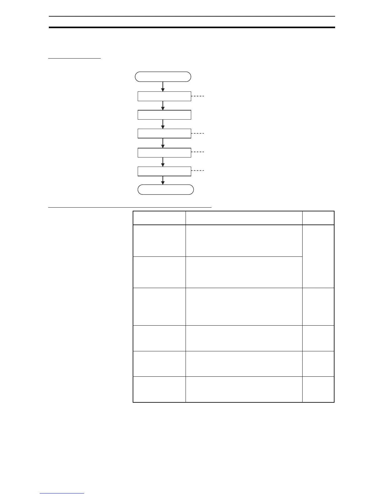
Typical Startup Procedure
Using the S8AS's Keys
Summary of Application Objectives and Settings
Preparation
Installation and wiring
Power ON
Set parameters
Trial run in Test Mode
Verify operation
Actual operation
See Section 3 Installation and Wiring.
See Section 4 Initial Settings.
(S8AS-24006N/48008N parameters
cannot be changed.)
See Section 5 Trial Run.
Branch outputs that will not be used can be
set to OFF (disconnected.)
Verify proper operation while monitoring status in Run Mode.
Desired objective/
usage
Settings Details
Use as a circuit
breaker with overcur-
rent tripping.
In Setting Mode, set the abnormal current trip-
ping threshold (C-V) for the branch output being
used and set the abnormal current tripping
detection setting (C-T) to standard detection
(USU).
p. 30,
p. 62
Use as a circuit
breaker for short-cir-
cuit current protec-
tion.
In Setting Mode, set the abnormal current trip-
ping threshold (C-V) for the branch output being
used and set the abnormal current tripping
detection setting (C-T) to instantaneous detec-
tion (INS).
Detect a drop in
power supply volt-
age.
In Setting Mode, set the undervoltage detection
threshold (V-U). Take the alarm signal from the
Undervoltage Detection Output (LOW) terminal.
When an undervoltage is detected, the seven-
segment display will show error code A21 and
the LOW output photoswitch output will go OFF.
p. 29,
p. 50
p. 63
Apply a separate
time lag when con-
necting each branch
output.
In Setting Mode, set the startup sequence
(UPS).
p. 37,
p. 66
Apply a separate
time lag when cutting
off each branch out-
put.
In Setting Mode, set the shutdown sequence
(DWS) and enable the External Tripping Input
(TRG).
p. 38,
p. 67
Use the S8AS
replacement time for
better maintenance.
The seven-segment display and the LFE termi-
nal signal output can be used to check the esti-
mated replacement time using the maintenance
forecast monitor function.
p. 34,
p. 64