52
RS-485 Port Wiring Section 3-4
3-4 RS-485 Port Wiring
Wiring the RS-485
Port
S8AS models with communications have an RS-485 port that can be con-
nected with a host computer or controller.
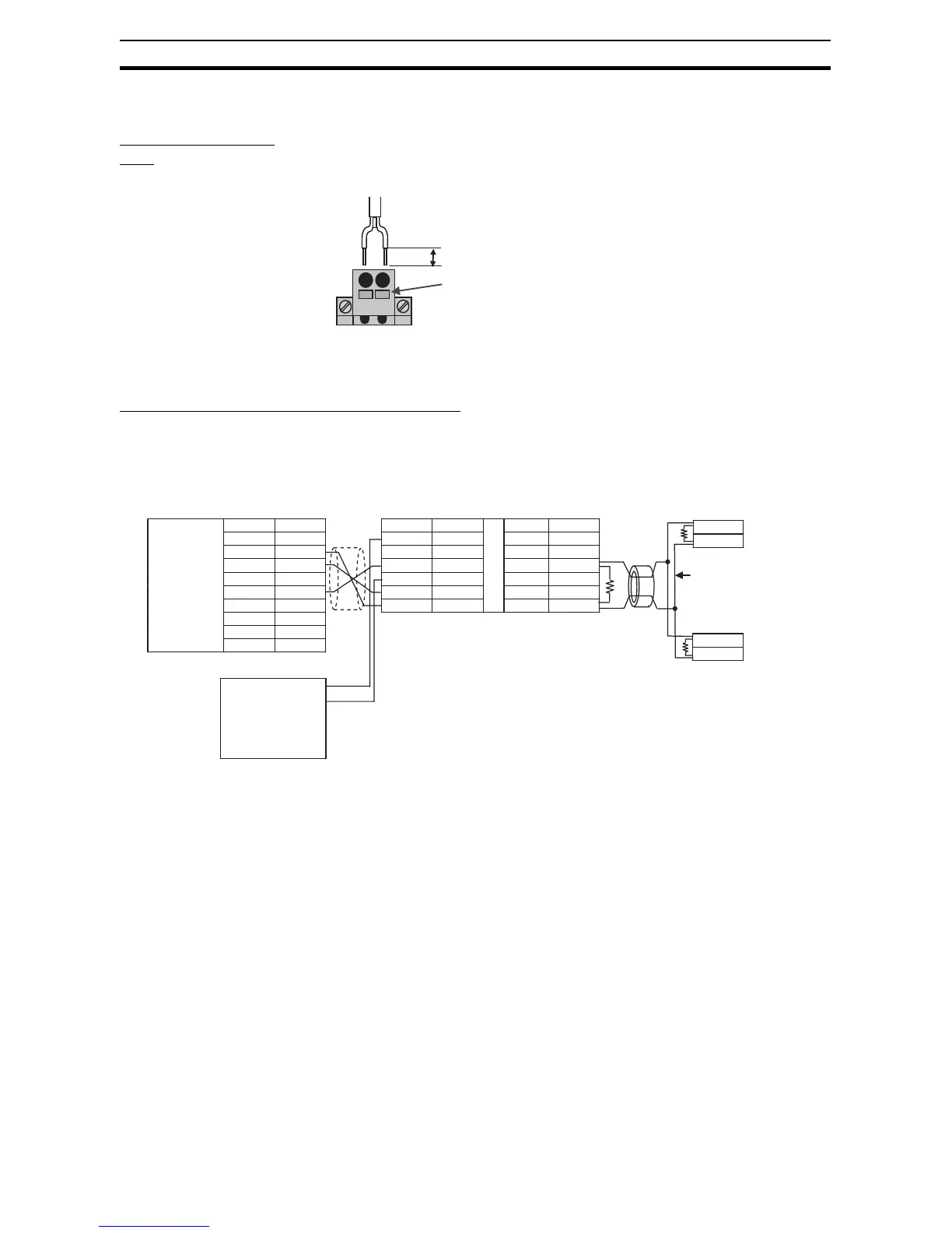
Example Connection to a Host Computer
• The connection format is 1:1 or 1:N. Up to 32 nodes can be connected to
a host computer.
• Insert a Cramp Filter (E04SR301334 manufactured by SEIWA) in the
cable as a countermeasure against noise.
• The node on each end of the transmission path, including the host com-
puter, must be specified as an end node (i.e., terminating resistor must be
connected.) Use terminating resistor of 120 Ω (1/2 W) with a combined
resistance of at least 54 Ω.
• Make sure that the communications specifications are set to the same
values for the host computer and the S8AS. (Refer to 4-1 Parameter
Table .) When connecting in a 1:N format, make sure that the communica-
tions specifications except for the communications unit number are set to
the same values for all nodes. A unique communications unit number
must be set for each node.
• Strip 10 mm from the ends of the RS-
485 cable's wires.
• Press the terminal's release button all
the way in and insert the wire into the
round wire hole. When the wire is
inserted, be sure that the wire conduc-
tor is not exposed.
• Release the release button to lock the
wire in place.
• After wiring, verify that the wires are
securely locked in the terminals.
Press the Release
Button all of the
way in and insert
the wire.
10 mm
A (−)
B (+)
1 PWR SG 7
2 NC RDA(−)8
3 SG SDA(−)9
4 PWR NC 10
5 SD 11
6 RD 12
S8AS
CD 1
RD 2
SD 3
ER 4
SG 5
DR 6
RS 7
CS 8
C1 9
S8AS
RS-485
RS-485
Clamp filter
RDB(+)
SDB(+)
A(−)
B(+)
A(−)
B(+)
Computer
RS-232C
interface
Name
Pin
Name
Pin
K3SC-10
Power Supply
• AC model:
100 to 240 VAC
• DC model:
24 VDC or 24 VAC
(50 to 60 Hz)
Name
Pin
Note: Terminating resistor (120 Ω, 1/2 W recommended)
We recommend
twisting the RS-485
communications lines.
(See note.)
(See
note.)
(See
note.)