47
Power Supply and Input/Output Wiring Section 3-3
3-3 Power Supply and Input/Output Wiring
Wiring Precautions • When wiring, cover the top of the S8AS to prevent wire strands from
entering. After completing the wiring, be sure to remove the cover to avoid
overheating.
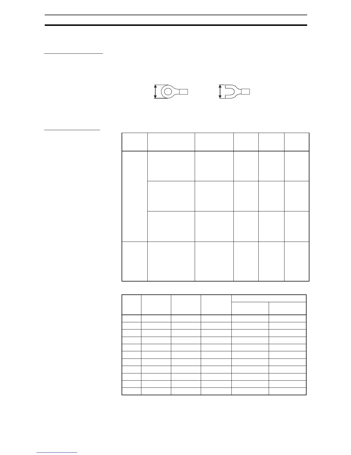
• Use the following crimp terminals on the power input wires and tighten the
terminal screws to the specified torque.
AC input terminals and protective earth (PE) terminals: M3.5
Negative branch output terminals: M4
Selecting the Wire
Refer to the following table when selecting wire to use for the power supply.
8 mm max.
8 mm max.
Terminals Name Recommended
wire diameter
Wire type Torque Wire
stripping
length
Screw ter-
minals
AC input terminals
and protective earth
(PE) terminal
AWG14 to
AWG16 (Cross-
section area:
1.309 to
2.081 mm
2
)
Solid or
stranded
1.08 N·m
(9.6 in lb)
8 to
10 mm
Branch output termi-
nals (−), UL Stan-
dard
AWG12 to
AWG14 (Cross-
section area:
2.081 to
3.309 mm
2
)
Solid or
stranded
1.2 N·m
(10.6 in lb)
8 to
10 mm
Branch output termi-
nals (−), CSA Stan-
dard
AWG12 to
AWG20 (Cross-
section area:
0.517 to
3.309 mm
2
)
Solid or
stranded
1.0 N·m
(8.8 in lb)
8 to
10 mm
Screw-
less termi-
nals
Positive branch out-
put terminals, nega-
tive branch output
terminals, I/O signal
terminals, and com-
munications termi-
nals
AWG12 to
AWG24 (Cross-
section area:
0.2 to 2.5 mm
2
)
Solid or
stranded
--- 10 mm
AWG Cross-sec-
tional area
(mm
2
)
Configura-
tion
(wires/mm)
Voltage
drop per A
(mV/m)
Max. recommended current (A)
UL1007
(300 V 80°C)
UL1015
(600 V 105°C)
30 0.051 7/0.102 358 0.12 ---
28 0.081 7/0.127 222 0.15 0.2
26 0.129 7/0.16 140 0.35 0.5
24 0.205 11/0.16 88.9 0.7 1.0
22 0.326 17/0.16 57.5 1.4 2.0
20 0.517 26/0.16 37.6 2.8 4.0
18 0.823 43/0.16 22.8 4.2 6.0
16 1.309 54/0.18 14.9 5.6 8.0
14 2.081 41/0.26 9.5 --- 12.0
12 3.309 65/0.26 6.0 --- 22.0
10 5.262 104/0.26 3.8 --- 35.0