24
Specifications Section 2-3
Note (1) Do not use an inverter output for the Power Supply. Inverters with an out-
put frequency of 50/60 Hz are available, but the rise in the internal tem-
perature of the Power Supply may result in ignition or burning.
(2) Refer to Derating Curve on page xiv for details.
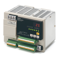
(3) If the output voltage adjuster (V. ADJ) is turned, the voltage will increase
by more than 10% of the voltage adjustment range. When adjusting the
output voltage, confirm the actual output voltage from the Power Supply
and be sure that the load is not damaged. If the output voltage exceeds
28.8 V, all branch outputs will be cut off.
(4) Rated input and output conditions: Rated input voltage, rated frequency,
rated output voltage, rated total output current, and maximum cutoff out-
put current.
(5) 100% load conditions: Rated output voltage, rated total output current,
and maximum cutoff output current.
Others Ambient operating temperature Refer to the derating curve (no icing or condensation). (See note 2.)
Storage temperature −25 5o 65°C
Ambient operating humidity 25% to 85% (storage: 25% to 90%)
Withstand voltage 3.0 kVAC for 1 min between all input terminals collectively and all branch out-
put, all I/O signal, and all communications terminals collectively (Detection cur-
rent: 20 mA)
2.0 kVAC for 1 min between all inputs and protective earth (Detection current:
20 mA)
1.0 kVAC for 1 min between protective earth and all branch output, all I/O sig-
nal, and all communications terminals collectively (Detection current: 20 mA)
500 VAC for 1 min between all branch output and all I/O signal/communications
terminals collectively (Detection current: 20 mA)
500 VAC for 1 min between all I/O signal terminals collectively and communica-
tions terminals collectively (Detection current: 20 mA)
500 VAC for 1 min between all I/O signal terminals collectively and all output
signal terminals collectively (detection current: 20 mA)
Insulation resistance 100 MΩ min. at 500 VDC between the protective earth terminal or all input ter-
minals collectively and all branch output, all I/O signal, and all communications
terminals collectively
Vibration resistance No abnormality after 10 to 55 Hz at 0.375-mm single amplitude for 2 h each in 3
directions.
Shock resistance
No abnormality after 150 m/s
2
3 times each in 6 directions.
Output indicator Provided (Color: green)
Conducted EMI Conforms to EN 61204-3 Class A and FCC Class A.
Radiated EMI Conforms to EN 61204-3 Class A.
Safety standards cULus: UL508 (Listing. Class2: Per UL1310), CSA C22.2 No.107.1 (Class2: Per
CSA C22.2 No.223)
cURus: UL60950-1, CSA C22.2 No.60950-1
EN: EN50178, EN60950-1
VDE: VDE0160, VDE0805 Teil1
Weight 1,600 g max.
Item Model S8AS-24006 S8AS-24006N S8AS-24006R