2-19
H Wiring on the Input Side of the Main Circuit
D Installing a Molded-case Circuit Breaker
Always
connect the power input terminals (R/L1, S/L2, and T/L3) and power supply via a
molded case circuit breaker (MCCB) suitable to the Inverter.
•Choose an MCCB with a capacity of 1.5 to 2 times the Inverter’s rated current.
•For the MCCB’s time characteristics, be sure to consider the Inverter’s overload
protection (one minute at 150% of the rated output current).
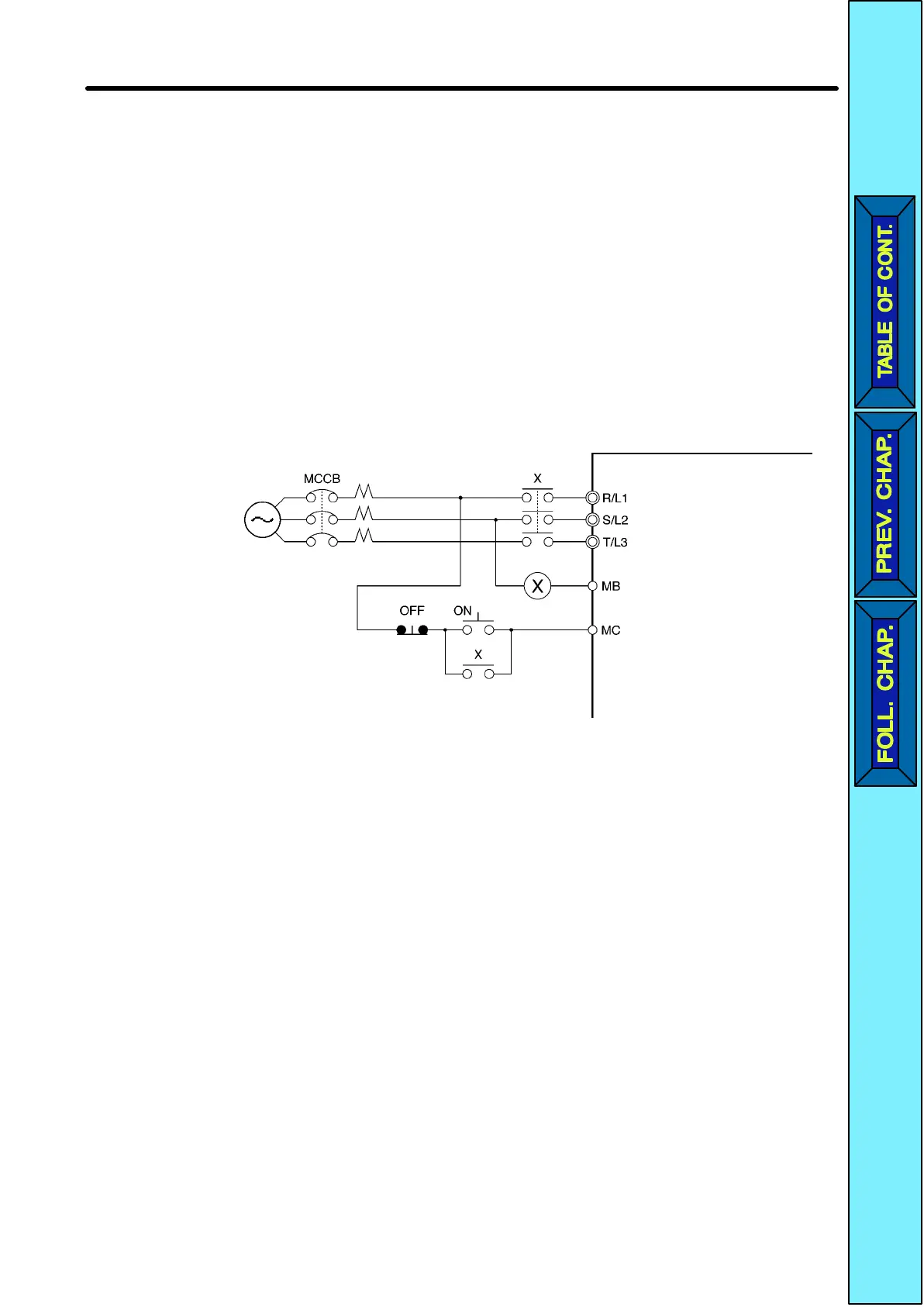
•If
the MCCB is to be used in common among multiple Inverters, or other devices, set up
a
sequence such that the power supply will be turned of
f by a fault output, as shown in
the following diagram.
3-phase/Single-
phase 200 VAC
Power
supply
Inverter
Fault output
(NC)
D Installing a Ground Fault Interrupter
Inverter
outputs use high-speed switching, so high-frequency leakage
current is gener
-
ated.
In
general, a leakage current of approximately 100 mA will occur for each Inverter (when
the power cable is 1 m) and approximately 5 mA for each additional meter of power
cable.
Therefore,
at the power supply input area, use a special-purpose breaker for Inverters,
which
detects only the
leakage current in the frequency range that is hazardous to hu
-
mans and excludes high-frequency leakage current.
Design Chapter
2
 Loading...


