5-22
H Operation in 3-wire Sequence (n37 = 0)
•The
Inverter operates in 3-wire sequence by setting n37 for multi-function input 2 to 0.
•Only
n37 can be set to 0 (3-wire sequence). By making this setting, the set value in n36
is ignored and the following settings are forcibly made.
S1: RUN input (RUN when ON)
S2: STOP input (STOP when OFF)
S3: Forward/Reverse rotation command (OFF: Forward; ON: Reverse)
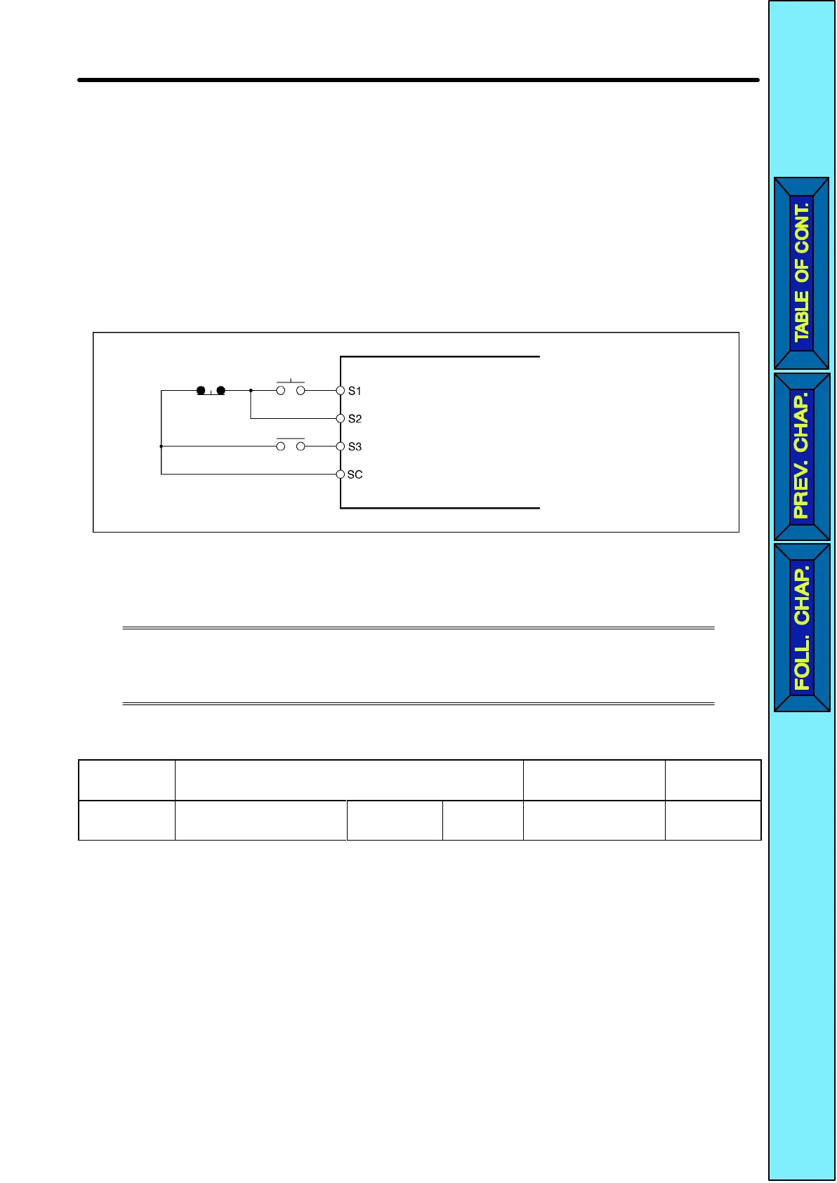
•The following diagram shows a wiring example of the terminals in 3-wire sequence.
Stop switch
(NC)
Operation
switch (NO)
Direction switch
RUN input (RUN with the STOP switch and RUN switch closed)
STOP input (with the STOP switch opened)
Forward/Reverse
rotation command (Forward rotation with the direction
switch opened and reverse rotation with the direction switch closed)
Sequence input common
5-9-2 Multi-function Output
The
3G3JV incorporates
two multi-function output terminals (MA and MB).
Output
from these terminals has a
variety of functions according to the ap
-
plication.
H Selecting the Multi-function Output (n40)
n40 Multi-function Output (MA/MB and MC) Changes during
operation
No
Setting
range
0 to 7, 10 to 17
(see note)
Unit of
setting
1 Default setting 1
Note Do not set values outside the above setting ranges.
Basic Operation Chapter
5
 Loading...


