106
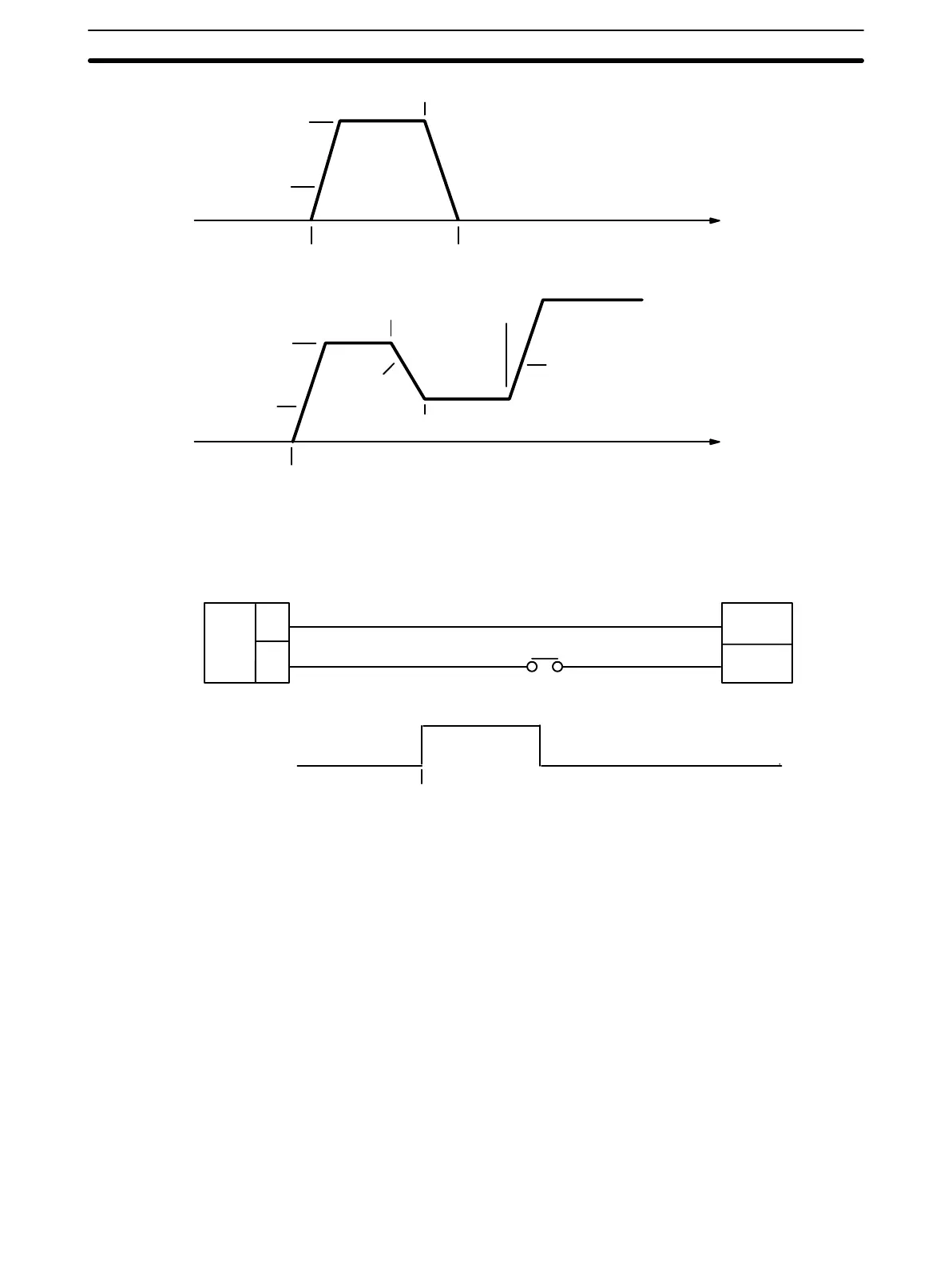
Acceleration
START
Time
Deceleration
Acceleration
Acceleration
Time
STOP (command executed)
Target speed #1
End position (positioning stops)
START
CHANGE SPEED (command executed)
Target speed #1
Target speed #2
Target speed #3
Connection for External Interrupt Signal
The signal level’s rising edge is taken as the input signal.
External input pin no.
19
A
B
External interrupt signal
1
0
Interrupt signal received
DC power supply
24 V
0 V
The setting of pin #6 on the back-panel DIP switch determines the function of
bit 06 of IR word n. If pin #6 is ON, the function of bit 06 is determined by pin
#7. If pin #6 is OFF, bit 06 defines the response to external interrupts as fol-
lows:
0: STOP executed in response to external interrupts
1: CHANGE SPEED executed in response to external interrupts
If pin #6 is ON and pin #7 is OFF, STOP is executed in response to external
interrupts. If pin #6 and pin #7 are both ON, CHANGE SPEED is executed in
response to external interrupts. The external interrupt signal is acknowledged
on its rising edge.
There are thus two ways to execute STOP: through an external interrupt or
through the command bit, bit 15 of IR word n. Both of these methods are
available at the same time if bit 06 of word n is set to 0 and pin #6 on the
back-panel DIP switch is OFF, or if pin #6 is ON and pin #7 is OFF.
There are also two ways to execute CHANGE SPEED: through an external
interrupt or, if pin #6 is ON, directly by using bit 06 of word n as the command
DIP Switch Settings
External Interrupt Commands Section 4–11