37
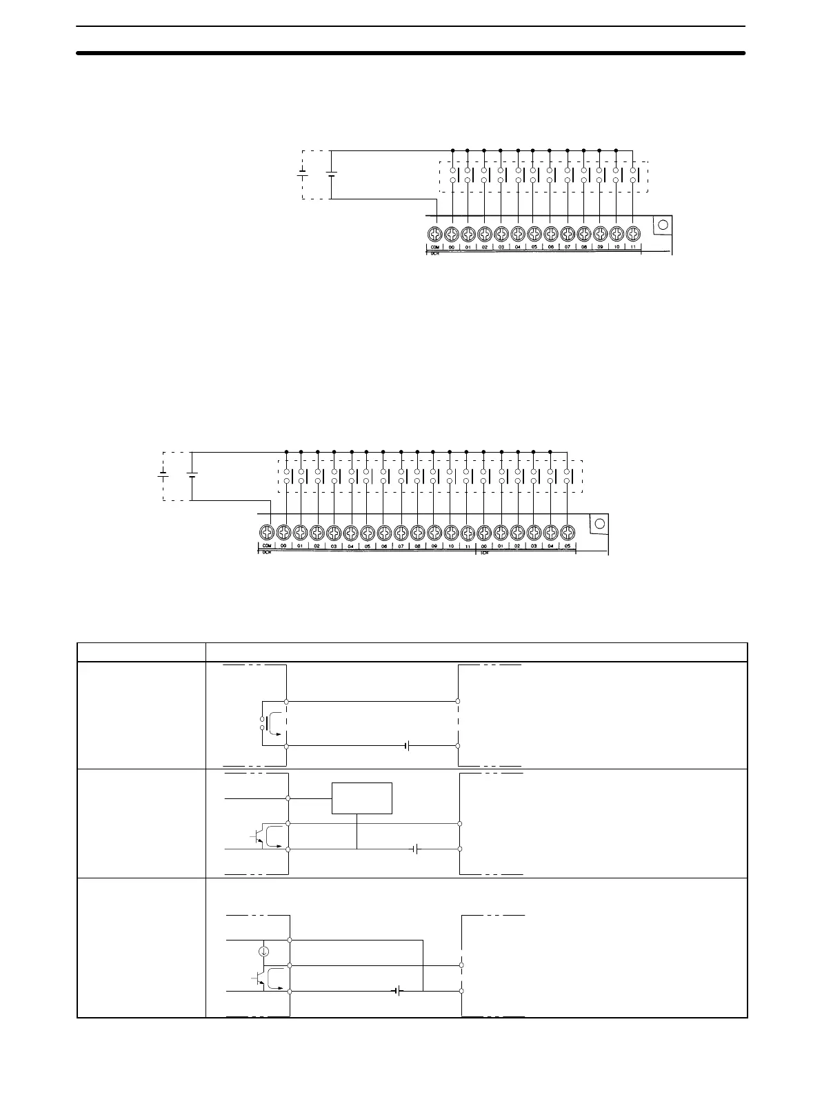
This diagram shows the input configuration for CPM1-20CDR- CPU Units and
CPM1-20EDR Expansion I/O Unit.
Input devices
COM
24 VDC
Note For details regarding CPM1A-20EDT/EDT1 Expansion I/O Unit connections,
refer to the CPM1A Programmable Controllers Operation Manual (W317).
CPM1-30CDR-(-V1) CPU Units This diagram shows the input configuration for CPM1-30CDR-(-V1)
CPU Units.
Input devices
COM
24 VDC
Input Devices The following table shows how to connect various input devices.
Device Circuit Diagram
Relay output
IN
COM (+)
Relay
5 mA/12 mA CPM1
NPN open collector
0 V
+
IN
COM (+)
Sensor
Sensor power
supply
Output
5 mA/12 mA
CPM1
NPN current output
0 V
+
IN
COM (+)
Constant current
circuit
Output
Use the same power supply for
the input and sensor.
+
5 mA/12 mA
CPM1
CPM1-20CDR- CPU Units
and CPM1-20EDR
Expansion I/O Unit
Wiring and Connections
Section 3-4