38
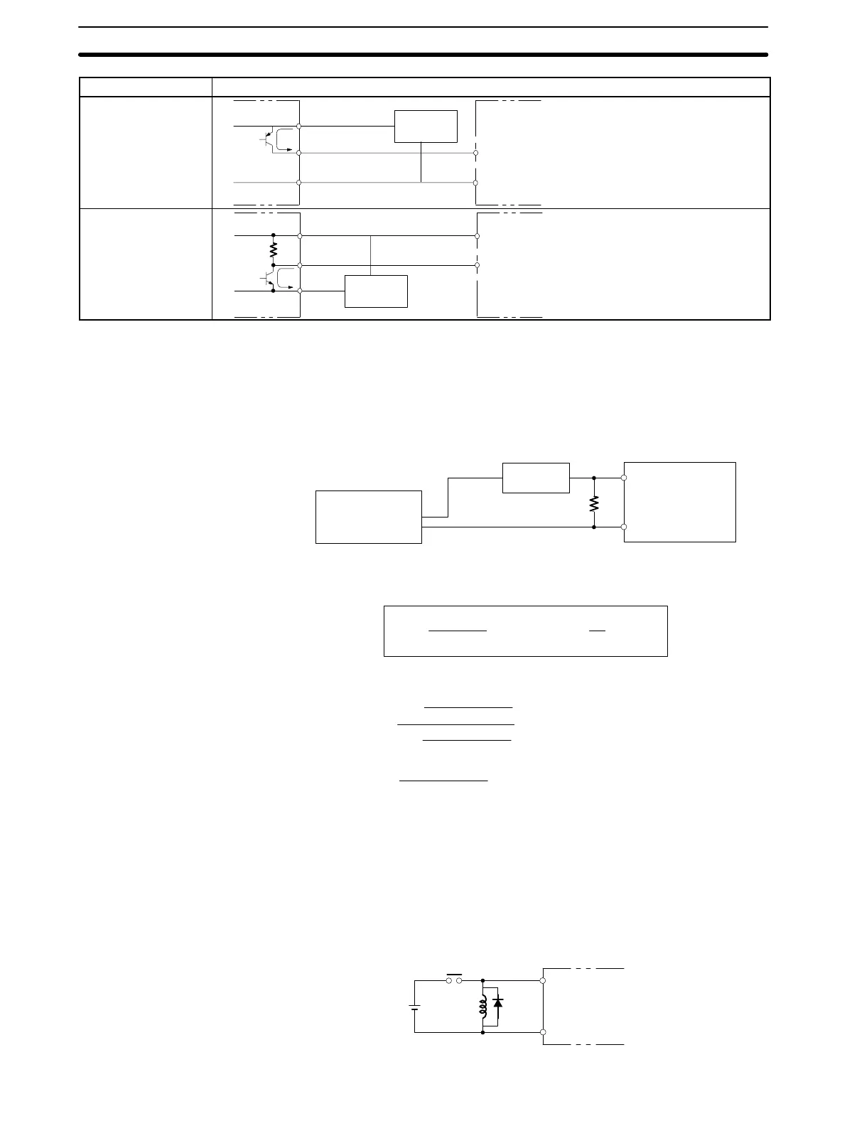
Device Circuit Diagram
PNP current output
Sensor power
supply
COM (–)
0 V
IN
+
Output
5 mA/12 mA
CPM1
Voltage output
Sensor power
supply
IN
COM (+)
0 V
Output
CPM1
+
Leakage Current (24 VDC) A leakage current can cause false inputs when using 2-wire sensors (proximity
switches or photoelectric switches) or limit switches with LEDs.
False inputs won’t occur if the leakage current is less than 1.0 mA (2.5 mA for
IN00000 to IN00002), but if the leakage current exceeds these values, insert a
bleeder resistor in the circuit to reduce the input impedance, as shown in the fol-
lowing diagram.
R
CPM1
Input power
supply
Bleeder resistor
2-wire sensor, etc.
I: Device’s leakage current (mA)
R: Bleeder resistance (kΩ)
W: Bleeder resistor’s power rating (W)
The equations above were derived from the following equations:
L
C
: CPM1’s input impedance (kΩ)
I
C
: CPM1’s input current (mA)
E
C
: CPM1’s OFF voltage (V) = 5.0 V
R +
L
C
5.0
I L
C
–5.0
kW max.
W +
2.3
R
Wmin.
I
R
Input voltage (24)
Input Current (I
C
)
R )
Input voltage (24)
Input Current (I
C
)
x OFF voltage (E
C
:5.0)
W y
Input voltage (24)
R
Input voltage (24) tolerance (4)
Refer to 2-1-3 I/O Specifications for details on the values L
C
, I
C
, and E
C
.
The input impedance, input current, and OFF voltage may vary depending on the
input being used. (IN00000 through IN00002 have different values.)
Inductive Loads When connecting an inductive load to an input, connect a diode in parallel with
the load. The diode should satisfy the following requirements:
1, 2, 3... 1. Peak reverse-breakdown voltage must be at least 3 times the load voltage.
2. Average rectified current must be 1 A.
IN
COM
Diode
CPM1
Wiring and Connections
Section 3-4