5-16
5
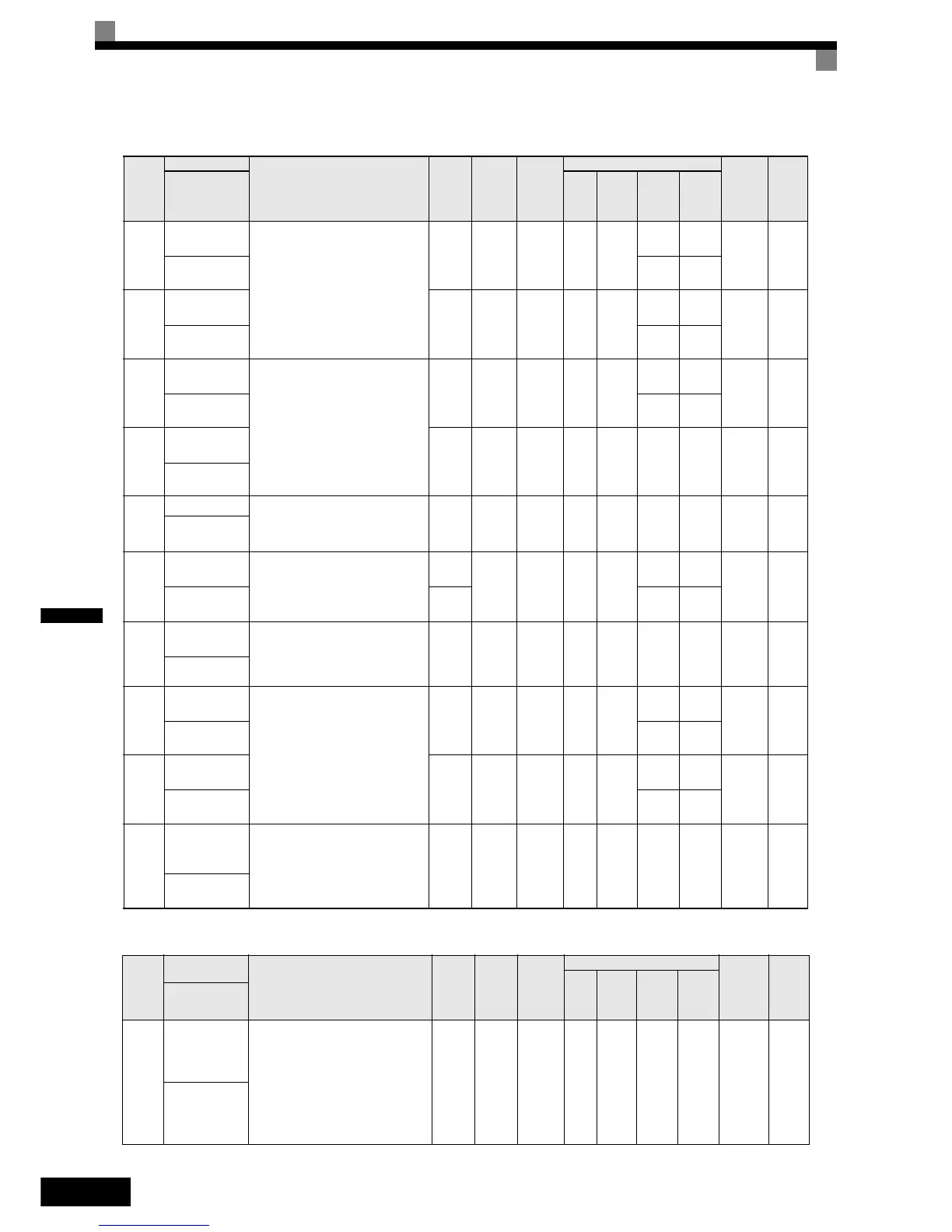
Speed Control (ASR): C5
Carrier Frequency: C6
Param
eter
Num-
ber
Name
Description
Set-
ting
Range
Fac-
tory
Setting
Change
during
Opera-
tion
Control Methods
MEMO-
BUS
Register
Page
V/f
Open
Loop
Vector
Closed
Loop
Vector
Closed
Loop
Vector
(PM)
Display
C5-01
ASR propor-
tional (P) gain 1
Set the proportional gain 1 and the
integral time 1 of the speed control
loop (ASR) for the maximum fre-
quency.
0.00 to
300.00
i
Yes - -
Q
40.00
-
21BH 6-32
ASR P Gain 1 -
Q
3.00
C5-02
ASR integral (I)
time 1
0.000
to
10.000
sec
i
Yes - -
Q
0.500
-
21CH 6-32
ASR I Time 1 -
Q
0.300
C5-03
ASR propor-
tional (P) gain 2
Set the proportional gain 2 and the
integral time 2 of the speed control
loop (ASR) for the minimum fre-
quency.
The setting is active only for accel-
eration.
0.00 to
300.00
i
Yes - -
Q
20.00
-
21DH 6-32
ASR P Gain 2 -
Q
3.00
C5-04
ASR integral (I)
time 2
0.000
to
10.000
sec
0.500 s Yes - - Q Q 21EH 6-32
ASR I Time 2
C5-06
ASR delay time
Sets the ASR output delay time.
0.000
to
0.500
0.020 s No - - - A 220H 6-32
ASR Gain SW
Freq
C5-07
ASR switching
frequency
Sets the frequency for switching
between Proportion Gain 1, 2,3 and
Integral Time 1, 2, 3.
0.0 to
120.0
i
No - -
Q
0.0 Hz
-
221H 6-32
ASR Gain SW
Freq
0.0 to
100.0
-
Q
2.0 %
C5-08
ASR integral (I)
limit
Set the parameter to a small value to
prevent any radical load change. A
setting of 100% is equal to the max-
imum output frequency.
0 to
400
400% No - - A A 222H 6-32
ASR I Limit
C5-09
ASR propor-
tional (P) gain 3
Set the proportional gain 3 and the
integral time 3 of the speed control
loop (ASR) for the minimum fre-
quency.
The settings is active for decelera-
tion only.
0.00 to
300.00
i
Yes - -
Q
40.00
-
22EH 6-32
ASR P Gain 3 -
Q
3.00
C5-10
ASR integral (I)
time 3
0.000
to
10.000
sec
i
Yes - -
Q
0.500
-
231H 6-32
ASR I Time 3 -
Q
0.300
C5-15
ASR gain for
encoder offset
tuning
Sets the ASR P gain which is used
for the encoder offset tuning if Hip-
erface or EnDat encoders are used.
0.00 to
300.00
5.00 No - - - A 238H 6-32
Pullin ASR
Pgain
Param
eter
Num-
ber
Name
Description
Set-
ting
Range
Fac-
tory
Setting
Change
during
Opera-
tion
Control Methods
MEMO-
BUS
Register
Page
V/f
Open
Loop
Vector
Closed
Loop
Vector
Closed
Loop
Vector
(PM)
Display
C6-02
Carrier fre-
quency selec-
tion 1
Selects the carrier frequency for
Induction motor control modes.
1:2 kHz
2:5 kHz
3:8 kHz
4:10 kHz
5:12.5 kHz
6:15 kHz
1 to 6 3 No A A A - 224H 6-2
CarrierFreq Sel