5-27
5
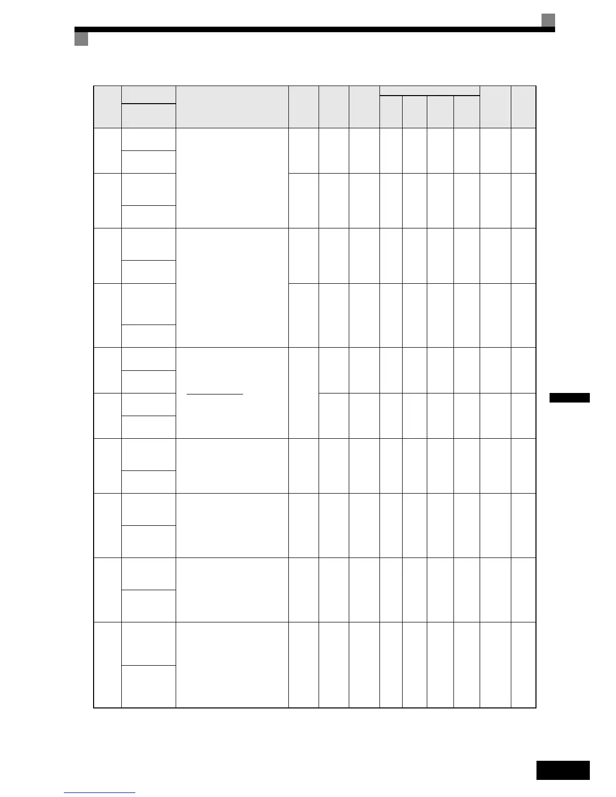
F1-08
Overspeed
detection level
Sets the overspeed detection
method.
Motor speeds that continue to
exceed the value set in F1-08 (set
as a percentage of the maximum
output frequency) for the time set
in F1-09 are detected as overspeed
faults.
0 to 120 115% No - - A A 387H 6-74
PG Overspd
Level
F1-09
Overspeed
detection delay
time
0.0 to
2.0
0.0 s No - - A A 388H 6-74
PG Overspd
Time
F1-10
Excessive
speed deviation
detection level
Sets the speed deviation detection
method.
Any speed deviation above the F1-
10 set level (set as a percentage of
the maximum output frequency)
that continues for the time set in
F1-11 is detected as a speed devia-
tion.
The speed deviation is the differ-
ence between actual motor speed
and the speed reference command.
0 to 50 10% No - - A A 389H 6-74
PG Deviate
Level
F1-11
Excessive
speed deviation
detection delay
time
0.0 to
10.0
0.5 s No - - A A 38AH 6-74
PG Deviate
Time
F1-12
Number of PG
gear teeth 1
Sets the number of teeth on the
gears if there are gears between the
PG and the motor.
A gear ratio of 1 will be used if one
of these parameters is set to 0.
0 to
1000
0No--ANo38BH6-73
PG#Gear
Teeth1
F1-13
Number of PG
gear teeth 2
0No--ANo38CH6-73
PG#Gear
Teeth2
F1-14
PG open-cir-
cuit detection
delay time
Used to set the PG disconnection
detection time. PGO will be
detected if the detection time
exceeds the set time.
0.0 to
10.0
2.0 s No - - A A 38DH 6-73
PGO Detect
Time
F1-18
DV3 fault
detection selec-
tion
Sets the number of scans (5ms)
until a DV3 fault (wrong direction)
is detected.
0:No DV3 detection
n: A DV3 fault is detected after n x
5msec.
0 to 5 1 No - - No A 3ADH 6-74
DV3 detect sel
F1-19
DV4 fault
detection selec-
tion
Sets the number of pulses until a
DV4 fault (wrong direction) is
detected.
0:No DV4 detection
n: A DV3 fault is detected after n
pulses.
0 to
5000
1024 No - - No A 3AEH 6-74
DV4 detect sel
F1-21
Absolute
encoder resolu-
tion
Sets the serial line resolution for
absolute encoders (Hiperface or
EnDat).
0:16384
1:32768
2:8192
(if EnDat is selected (n8-35=5),
F1-21 is fixed to 2)
0 to 2 2 No - - - A 3B0H 6-73
PG-F2 Resolu-
tion
Param-
eter
Num-
ber
Name
Description
Setting
Range
Factory
Setting
Change
during
Opera-
tion
Control Methods
MEMO-
BUS
Register
Page
V/f
Open
Loop
Vector
Closed
Loop
Vector
Closed
Loop
Vector
(PM)
Display
PG Input Pulses x 60
F1-01
F1-13
F1-12
x