6-6
6
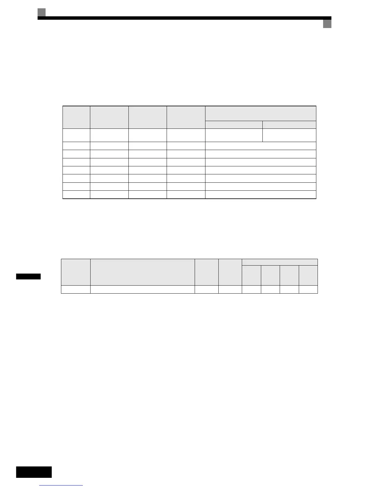
Speed Selection Table
The following table shows the combinations of the digital input and the according speed.
If b1-02 is set to “1”, speed 1 is input as analog reference at terminal A1 or Channel CH1 of an analog input
option card AI-14B if it is installed.
If an AI-14B option card is used and the functions for channel CH2 and CH3 are set to “Auxiliary Frequency
2” (H3-05/09=2) and “Auxiliary Frequency 3” (H3-05/09=3).
Nominal / Leveling Speed Detection with Multi Speed Inputs
Using this function the inverter can distinguish between the nominal and leveling speed when the speed selec-
tion is done by multifunction inputs which is required by other functions like the ASR controller, short floor
operation and slip compensation for V/f control.
Related Parameters
If the
• reference speed >= S3-04 the selected speed is regarded as nominal speed
• reference speed < S3-04 the selected speed is regarded as leveling speed
Speed
Multi-step Speed
Command 1
Multi-step Speed
Command 2
Multi-step Speed
Command 3
Selected Frequency
d1-18 = 0 d1-18 = 3
1 OFF OFF OFF
Frequency reference 1 d1-01
or A1/AI-14B CH1
Stop
2 ON OFF OFF Frequency reference 2, d1-02 or AI-14B CH2
3 OFF ON OFF Frequency reference 3, d1-03 or AI-14B CH3
4 ON ON OFF Frequency reference 4, d1-04
5 OFF OFF ON Frequency reference 5, d1-05
6 ON OFF ON Frequency reference 6, d1-06
7 OFF ON ON Frequency reference 7, d1-07
8 ON ON ON Frequency reference 8, d1-08
Parameter
No.
Name
Factory
Setting
Change
during
Operation
Control Methods
V/f
Open
Loop
Vector
Closed
Loop
Vector
Closed
Loop
Vector
(PM)
S3-04 Nominal/Leveling speed detection level 0.00 Hz No A A A A