6-16
6
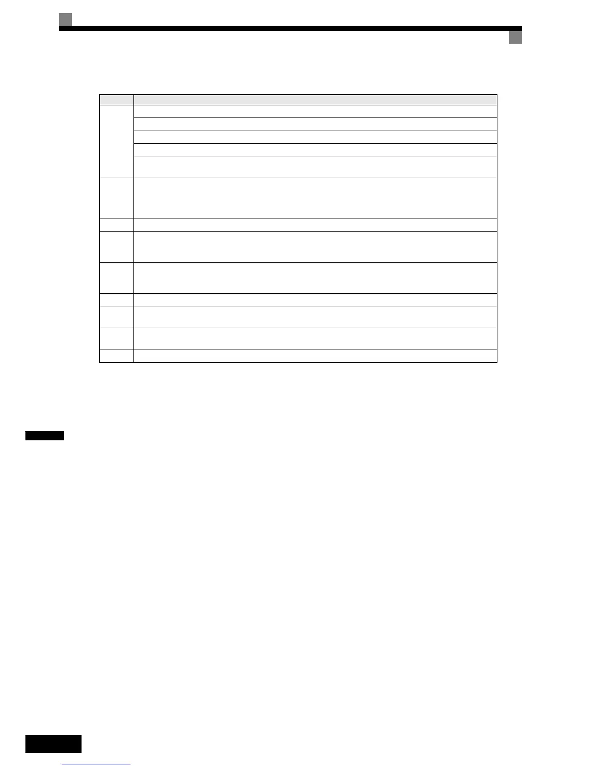
The timing chart above is divided in time zones. The following table explains the sequence in each time zone
Torque Limit Fade Out Function (Closed Loop Vector for PM)
The torque limit fade out function smoothly reduced the torque limit to 0 after the zero speed time at stop has
elapsed. It thereby can help to prevent shocks or vibrations when the motor stops and the brake is closed. The
used time constant can be set in parameter S1-31. The function can be used in Closed Loop Vector control for
PM motors only (A1-02 = 6).
Zero Speed Control / Zero Servo (position lock)
In Closed Loop Vector control the inverter uses zero speed or zero servo control during the brake open or close
procedure.
Zero Speed Control:
The inverter keeps the motor speed at zero, a roll-back is not compensated. This method is used for the start
with a torque compensation value by analog input. The strength of the control can be tuned using the ASR
parameters C5-. Refer to page 6-32, Automatic Speed Regulator (ASR) (Closed Loop Vector only) for tun-
ing details.
Zero Servo Control:
The inverter tries to keep the rotor position, i.e. a roll back is compensated. This method is used for the start
when no torque compensation is used and always for during stop (without and with torque compensation).
Additionally to the ASR parameters C5- the zero servo control can be tuned using the parameter S1-20
(Zero servo gain).
• Increase S1-20 if there is a rollback when the brake opens.
• Decrease S1-20 if vibrations occur when the zero servo function is active.
If a digital output is set to “Zero Servo End” (H2-=33), this output can be used to signalize, that the rotor
position is within a certain bandwidth around the zero position which can be set in parameter S1-21 (the band-
width is set in PG pulses and must be set 4 times of the allowable actual PG pulses).
Timing Description
t1
The inverter gets the direction signal (UP/DOWN)
The inverter gets the hardware base block signal disable signal (Not BB condition).
The inverter receives the speed reference signal.
The inverter sets the contactor close signal.
The inverter waits for the contactor confirmation signal. If no digital input is set to contactor confirmation
signal (H1-=86), the sequence is proceeded after exceeding the operation start delay time (S1-16).
t2
The zero speed control operation is started.
The analog torque compensation input is latched and the torque compensation value is increased from zero to the latch
value using the time constant set in parameter S1-22.
After reaching the torque compensation level at start, the inverter sets the brake open command.
t3 The brake opens and the zero speed operation (no position lock) is continued until S1-04 has elapsed.
t4
The speed is increased to the selected speed and is kept constant until the leveling speed is selected.
During acceleration, when the torque fade out speed level S1-29 is reached, the torque compensation value is fade out to 0
using the time constant set in S1-22.
t5
The speed is decreased to the leveling speed and is kept constant until the stop signal is given (depending on d1-18 either by
removing the direction signal, by removing the leveling signal or by deleting the speed inputs, see page 6-5, Speed Selection
Sequence Using Digital Inputs).
t6 The speed is decreased to the zero speed level.
t7
When the Zero Speed Level (S1-01) is reached, zero servo operation (position lock in Closed Loop) is applied for the time
set in S1-05. When the brake close delay time (S1-07) has elapsed, the brake open command is removed.
t8
The inverter continues the zero speed operation until the time S1-06 – S1-07 has elapsed. After that the inverter output is
shut down and the hardware base block signal must be set.
t9 After the output contactor open delay time (S1-19) has elapsed, the output contactor close signal is removed.