6-60
6
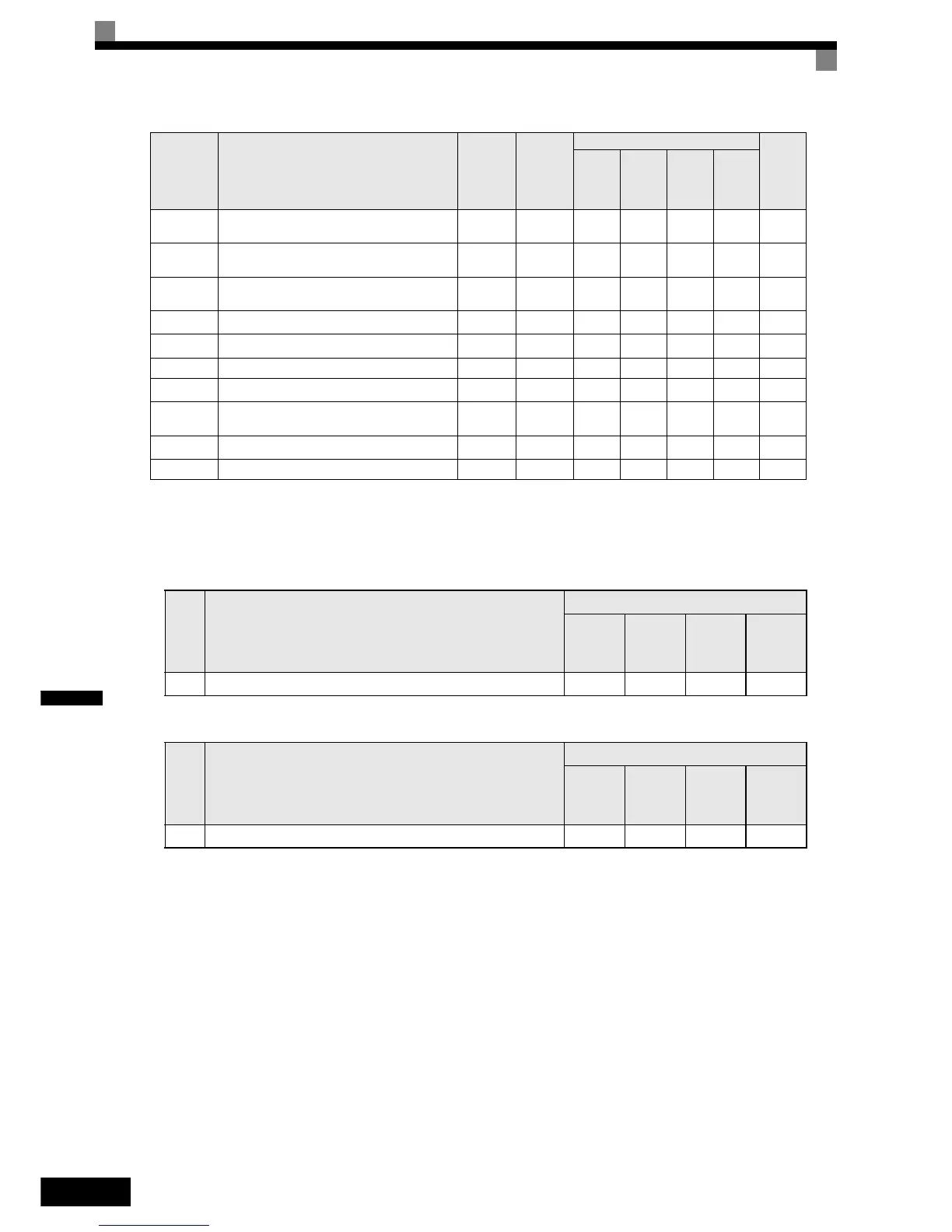
Multi-function Digital Inputs (H1-01 to H1-05)
Multi-function Digital Outputs (H2-01 to H2-03)
Setting Inverter Input Voltage (E1-01)
Set the Inverter input voltage correctly in E1-01 so that it matches the power supply voltage.
E2-04/
E4-04
Number of motor poles (Number of poles) 4 poles No -
Q/
A
Q/
A
-Yes
E2-05/
E2-05
Motor line-to-line resistance
3.333 Ω
*3
No AAA -Yes
E2-06/
E4-06
Motor leak inductance 19.3% No - A A - Yes
E2-07 Motor iron saturation coefficient 1 0.50 No - A A -
Ye s
*4
E2-08 Motor iron saturation coefficient 2 0.75 No - A A -
Ye s
*4
E2-09 Motor mechanical losses 0.0% No - - A - No
E2-10 Motor iron loss for torque compensation
130 W
*3
No A - - - No
E2-11/
E4-07
Motor rated output power
3.70 kW
*3
No
Q/
A
Q/
A
Q/
A
-Yes
E2-12 Motor iron saturation coefficient 3 1.30 No - A A -
Ye s
*4
F1-01 PG constant 1024 No - - Q Q Yes
*1. The value is valid for a 400V, 3.7kW inverter
*2. The value depends on the control mode. The given value is valid if V/f control is selected.
*3. All factory-set parameters are for a Yaskawa standard 4-pole motor.
The factory settings depend on Inverter capacity (the values shown are for a 400 V Class Inverter for 3.7 kW).
*4. Rotating tuning only
Set
Val ue
Function
Control Methods
V/f
Open
Loop
Ve ct or
Closed
Loop ´
Vector
Closed
Loop
Vector
(PM)
16 Motor 2 selection (OFF: Motor 1, ON: Motor 2) A A A -
Set
Val ue
Function
Control Methods
V/f
Open
Loop
Ve ct or
Closed
Loop ´
Vector
Closed
Loop
Vector
(PM)
1C Motor selection (OFF: Motor 1, ON: Motor 2) A A A -
Parameter
No.
Name
Factory
Setting
Change
during
Operation
Control Methods
Set by
Auto-
tuning
V/f
Open
Loop
Vector
Closed
Loop
Vector
Closed
Loop
Vector
for PM