6-78
6
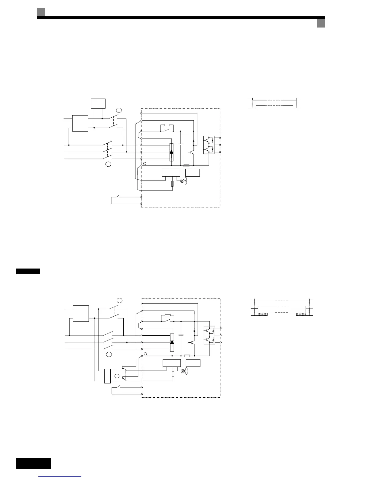
Rescue operation wiring examples
The following diagrams show some wirings examples for rescue operation.
Example 1: 1 Phase, 230 V UPS Power Supply
The contactors must be operated, so that contactor B is always opened, before A is closed. When the rescue
operation is finished, the contactor A must be opened, before B is closed.
If the UPS power is weak or Light load detection is not used, it can happen that the inverter trips with a UV2
fault. In this case increase the UPS power, use the light load detection function or use the configuration in
example 2.
Example 2: 1 Phase, 230 V UPS Power Supply, Low power UPS or Light Load detection not
used
The contactors must be operated, so that contactor B is always opened, before A and C are closed. Contactor C
can be closed after A but not before. When the rescue operation is disabled, the contactors A and C must be
opened, before B is closed.
UPS
1x230
VAC
L1
L2
L3
N
Elevator
Control
System
Inverter
R/L1
S/L2
T/L3
-
P0
N0
Sx
SC
W/T3
V/T2
U/T1
Control
circuit
Power Supply
B1
B2
A
B
Rescue Operation
Enable Input
Contactor A
Contactor B
Contactor Sequence
Wiring
UPS
1x230
VAC
L1
L2
L3
N
Inverter
R/L1
S/L2
T/L3
-
P0
N0
Sx
SC
W/T3
V/T2
U/T1
Control
circuit
Power Supply
B1
B2
A
B
Rescue Operation
Enable Input
Contactor Sequence
Wiring
Rectifier Diode
and Capacity
C
Contactor A
Contactor C
Contactor B