6-79
6
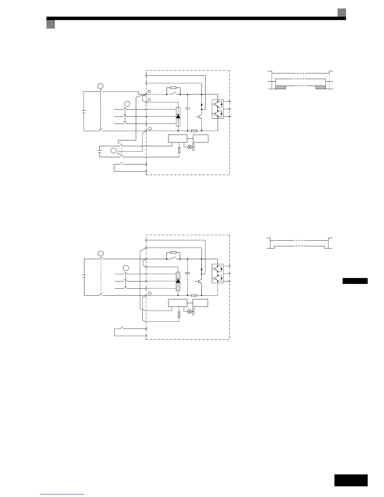
Example 3: Two Batteries, Main battery voltage lower than 280 VDC.
The contactors must be operated, so that contactor B is always opened, before A and C are closed. Contactor C
can be closed after A but not before. When the rescue operation is disabled, the contactors A and C must be
opened, before B is closed.
Example 4: Main battery voltage higher than 280 VDC.
The contactors must be operated, so that contactor B is always opened, before A is closed. When the rescue
operation is disabled, the contactor A must be opened, before B is closed.
Rescue Operation Speed
During rescue operation the speed is limited by the battery voltage using the following formula:
• for the 200 V class:
• for the 400 V class:
If the rescue speed reference (d1-15) is higher than the rescue operation speed limit, the output frequency is
automatically limited to the calculated limit. It prevents a voltage saturation and a possible motor stalling.
Precautions
Because of the possibly low DC bus voltage during rescue operation, the heatsink cooling fans may not work.
A continuous operation under this condition can result in over heat faults and inverter damage.
Main
Battery
R/L1
S/L2
T/L3
+1
-
P0
N0
Sx
SC
Inverter
Main power
Controller
Supply Battery
A
B
C
Rescue Operation
Enable Input
Wiring
W/T3
V/T2
U/T1
Control
circuit
Power Supply
B1
+2
B2
Contactor A
Contactor C
Contactor B
Contactor Sequence
L1
L2
L3
Inverter
Main power
B
Rescue Operation
Enable Input
Main
Battery
A
Wiring
Contactor A
Contactor B
Contactor Sequence
R/L1
S/L2
T/L3
-
P0
N0
Sx
SC
W/T3
V/T2
U/T1
Control
circuit
Power Supply
B1
B2
L1
L2
L3
Rescue Operation Speed Limit
DC Bus Voltage L2-11 Base frequency E1-04×
300 V 2×
---------------------------------------------------------------------------------------------------------------------
=
Rescue Operation Speed Limit
DC Bus Voltage L2-11 Base frequency E1-04×
600 V 2×
----------------------------------------------------------------------------------------------------------------------
=