6-88
6
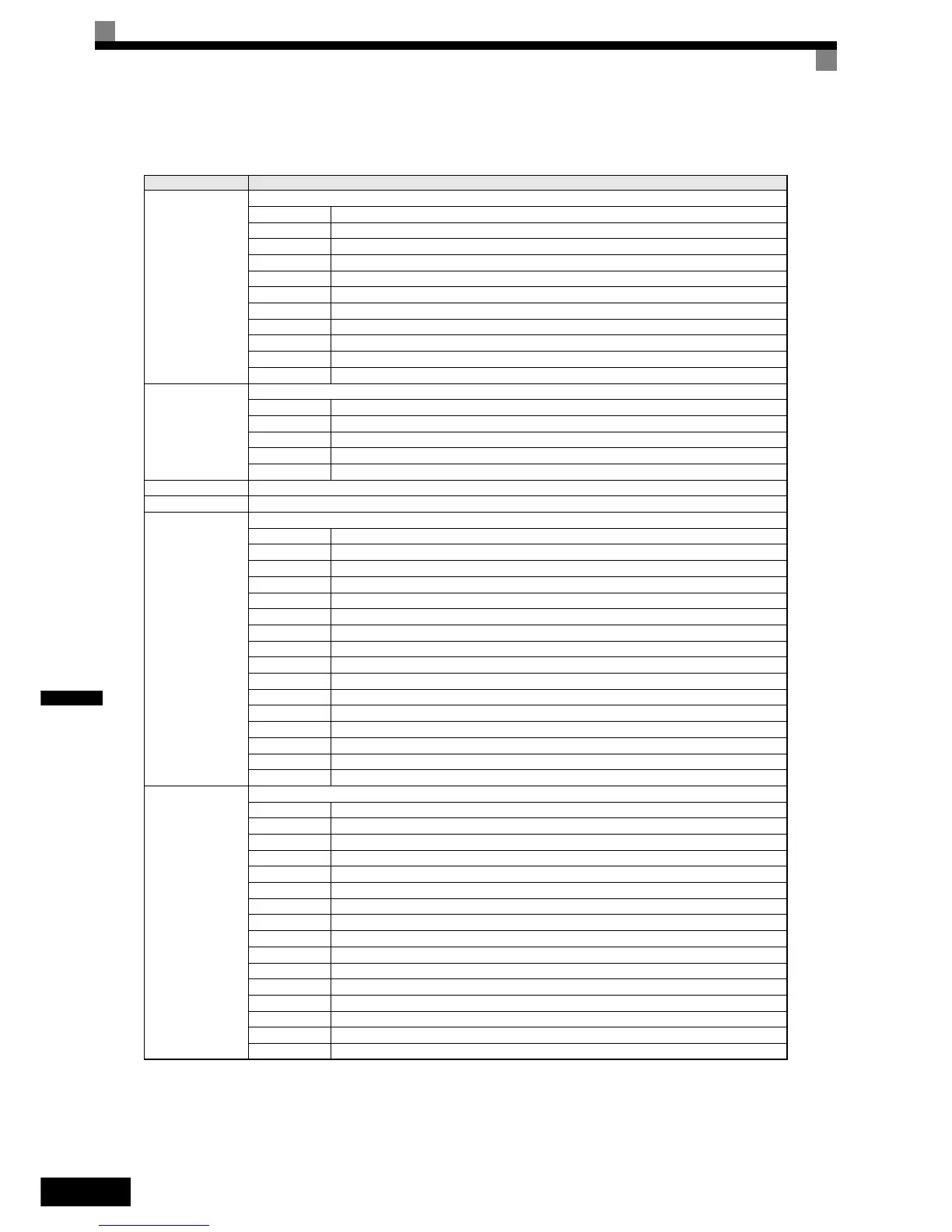
Monitor Data
The following table shows the monitor data. Monitor data can only be read.
Register Address. Contents
0010H
Inverter status signal
Bit 0 During run
Bit 1 Zero speed
Bit 2 During reverse operation
Bit 3 Reset signal active
Bit 4 During speed agree
Bit 5 Inverter ready
Bit 6 Minor fault
Bit 7 Major fault
Bits 8 to D Not used
Bit E ComRef status
Bit F ComCtrl status
0011H
Operator status
Bit 0 During OPE alarm
Bit 1 During fault
Bit 2 Operator in programming mode
Bit 3 0: Digital operator attached 1: PC connected
Bit 4 to F Not used
0012H OPE Fault Number
0013H Not used
0014H
Fault Content 1
Bit 0 PUF, DC bus fuse blown
Bit 1 UV1
Bit 2 UV2
Bit 3 UV3
Bit 4 Not used
Bit 5 GF, Ground fault
Bit 6 OC, Over current
Bit 7 OV, DC bus over voltage
Bit 8 OH, Inverter heatsink overheat pre-alarm
Bit 9 OH1, Inverter heatsink overheat
Bit A OL1, Motor overload
Bit B OL2, Inverter overload
Bit C OL3, Overtorque detection 1
Bit D OL4, Overtorque detection 2
Bit E RR, Internal braking transistor fault
Bit F RH, Inverter mounted braking resistor overheat
0015H
Fault Content 2
Bit 0 EF3, External fault set on terminal S3
Bit 1 EF4, External fault set on terminal S4
Bit 2 EF5, External fault set on terminal S5
Bit 3 EF6, External fault set on terminal S6
Bit 4 EF7, External fault set on terminal S7
Bit 5 Not used
Bit 6 Not used
Bit 7 OS, Overspeed detected
Bit 8 DEV, Speed deviation detected
Bit 9 PGO, PG disconnected
Bit A PF, Input phase loss
Bit B LF, Output open phase
Bit C OH3, Motor overheat pre-alarm (PTC analog input)
Bit D OPR, Digital operator disconnected
Bit E ERR, EPROM error
Bit F Not used