5-5
5
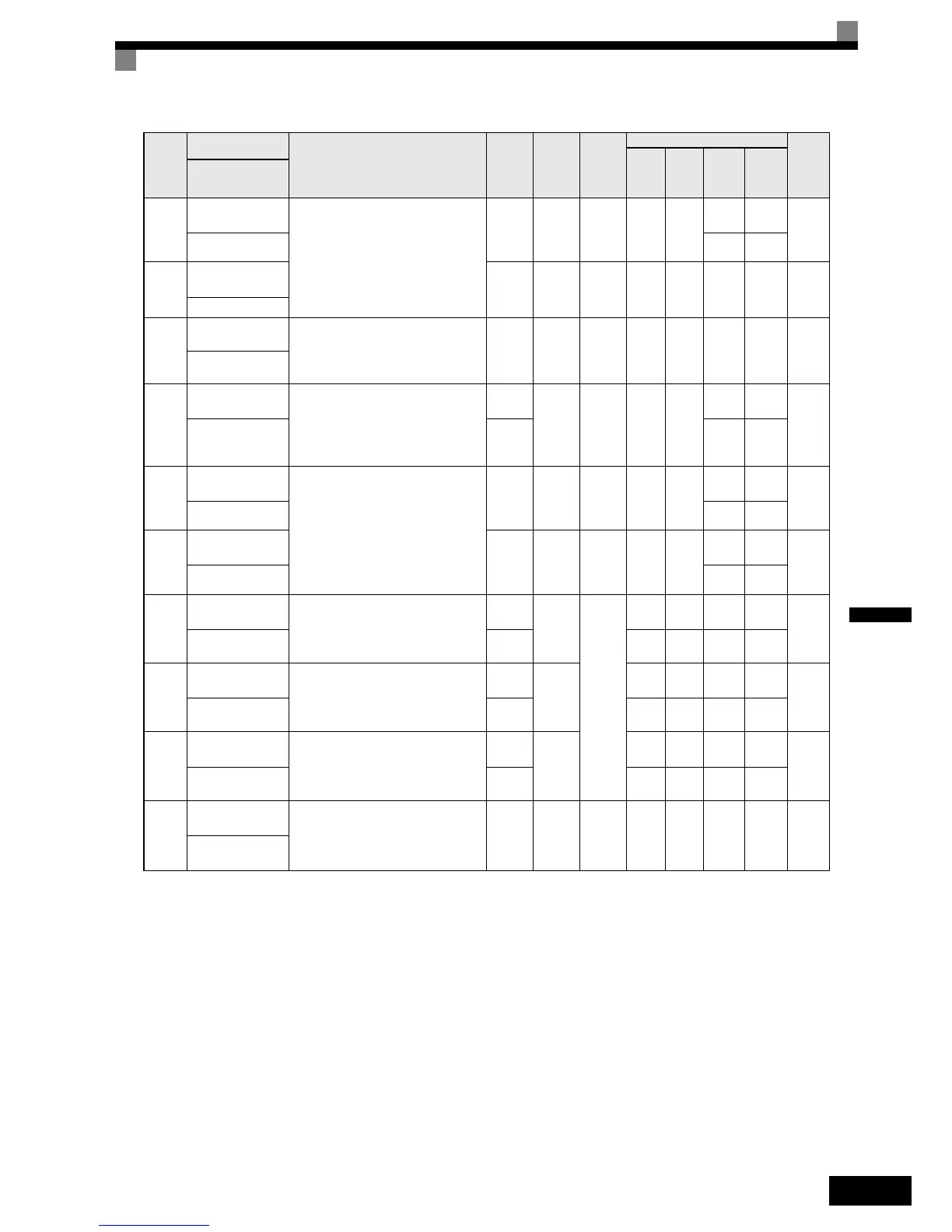
C5-03
ASR proportional
(P) gain 2
Set the proportional gain 2 and the inte-
gral time 2 of the speed control loop
(ASR) for the maximum frequency.
0.00 to
300.00
i
Yes - -
20.00 -
21DH
ASR P Gain 2 -6.00
C5-04
ASR integral (I)
time 2
0.000
to
10.000
0.500 s Yes - - Yes Yes 21EH
ASR I Time 2
C5-06
ASR delay time
Sets the filter time constant; the time
from the speed loop to the torque com-
mand output. Usually changing this set-
ting is not necessary.
0.000
to
0.500
0.020
sec
No - - - Yes 220H
ASR Delay Time
C5-07
ASR switching fre-
quency
Sets the frequency for switching
between Proportion Gain 1, 2,3 and
Integral Time 1, 2, 3.
0.0 to
50.0 Hz
i
No - -
0.0 Hz -
221H
ASR Gain SW Freq
0.0 to
100.0
%
- 2.0 %
C5-09
ASR proportional
(P) gain 3
Set the proportional gain 3 and the inte-
gral time 3 of the speed control loop
(ASR) for the minimum frequency.
The settings becomes active for deceler-
ation only.
0.00 to
300.00
i
Yes - -
40.00 -
22EH
ASR P Gain 3 - 12.00
C5-10
ASR integral (I)
time 3
0.000
to
10.000
i
Yes - -
0.500s
-
231H
ASR I Time 3 - 0.300s
d1-09
Nominal speed ref-
erence
Sets the frequency reference when the
nominal speed is selected by a digital
input.
0 to
120.00
i
Yes
50.00
Hz
50.00
Hz
50.00
Hz
-
288H
Nomin Speed vn
0 to
100.00
-- -
100.00
%
d1-14
Inspection speed
reference
Sets the frequency reference when the
inspection speed is selected by a digital
input
0 to
120.00
i
25.00
Hz
25.00
Hz
25.00
Hz
-
28FH
Inspect Speed vi
0 to
100.00
-- -
50.00
%
d1-17
Leveling speed ref-
erence
Sets the frequency reference when the
leveling speed is selected by a digital
input
0 to
120.00
i
4.00
Hz
4.00
Hz
4.00
Hz
-
292H
Level Speed vl
0 to
100.00
-- -8.00%
E1-01
Input voltage set-
ting
Sets the inverter input voltage. This set
value will be the basis for the protection
functions.
310 to
510
*2
400 V
*2
No Ye s Yes Yes Yes 300 H
Input
Voltage
Param-
eter
Num-
ber
Name
Description
Setting
Range
Factory
Setting
Change
during
Opera-
tion
Control Methods
MEMO
BUS
Regis-
ter
V/f
Open
Loop
Vector
Closed
Loop
Vector
Closed
Loop
Vector
(PM)
Display