5-7
5
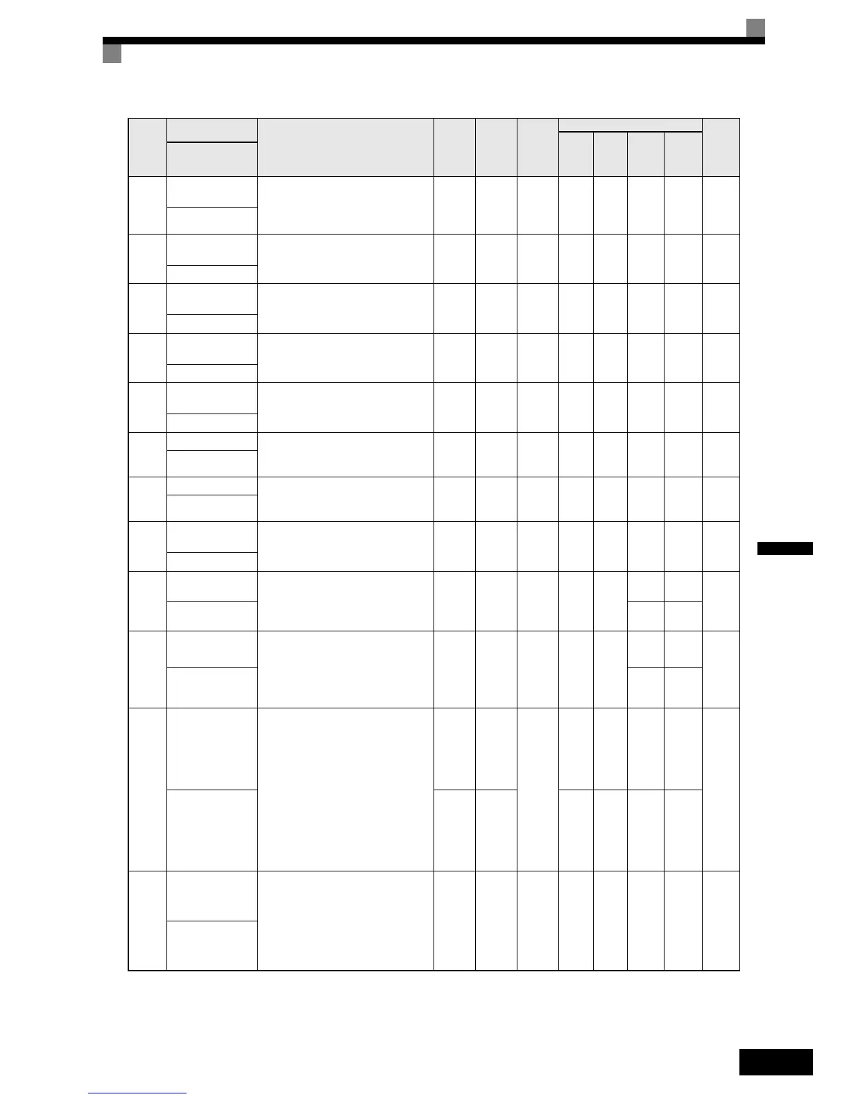
E2-11
Motor rated output
power
Sets the rated output power of the
motor.
This parameter is an input data for auto-
tuning.
0.00 to
650.00
3.70
kW
*4
No Ye s Yes Yes N o 318 H
Mtr Rated Power
E5-02
Motor rated output
power
Sets the rated output power of the
motor.
0.00 to
300.00
3.70
kW
*4
No - - - Yes 0C2H
Rated Power
E5-03
Rated Motor Cur-
rent
Sets the rated motor current.
0.00 to
200.00
7.31
A
*4
No - - - Yes 0C3H
Rated Current
E5-04
Number of motor
poles
Sets the motor pole number. 4 to 48 4 No - - - Yes 0C4H
Number of poles
E5-05
Motor terminal
resistance
Sets the motor line-to-line resistance
0.000
to
65.000
1.326
Ohm
*4
No - - - Yes 0C5H
Term resistance
E5-06
d-Axis Inductance
Sets the D-axis inductance.
0.00 to
300.00
19.11
mH
*4
No - - - Yes 0C6H
d-ax inductance
E5-07
q-Axis Inductance
Sets the Q-axis inductance.
0.00 to
600.00
26.08
mH
*4
No - - - Yes 0C7H
q-ax inductance
E5-09
Motor voltage con-
stant
Sets the voltage constant of the motor.
50.0 to
4000.0
478.6
mV
*4
No - - - Yes 0C9H
Voltage constant
F1-01
PG constant
Sets the number of PG pulses per revo-
lution
0 to
60000
i
No - -
Yes
1024
-
380H
PG Pulses/Rev -
Yes
2048
F1-05
PG rotation
0:Phase A leads with forward run com-
mand. (Phase B leads with reverse run
command.)
1:Phase B leads with forward run com-
mand. (Phase A leads with reverse
run command.)
0 or 1
i
No - -
0-
384H
PG Rotation Sel -1
L1-01
Motor protection
selection
Set to enable or disable the motor over-
load protection function using the elec-
tronic thermal relay.
0:Disabled
1:Protection for general purpose motor
(fan cooled)
2:Protection for frequency converter
motor (external cooled)
3:Protection for special vector control
motor
5:Permanent magnet constant torque
motor
0 to 3 1
No
Yes Ye s Ye s -
480H
MOL Select 0 or 5 5 Yes
n8-35
Magnetic pole
position detection
Sets the detection method for magnetic
pole position of a PM motor.
0:Automatic detection (applicable for
Yas ka w a I PM mo t or on ly )
4:Hiperface
y
Data
5:EnDat Data
0, 4 or
5
5No---Yes192H
Mag det sel
*1. The setting ranges for acceleration/deceleration times depends on the setting of C1-10 (Acceleration/deceleration Time Setting Unit). If C1-10 is set to 0,
the setting range is 0.00 to 600.00 (s).
*2. The given values are for a 400 V class Inverter.
*3. The setting range is from 10% to 200% of the Inverter rated output current. The given values are for a 3.7 kW 400 V Class Inverter.
*4. The factory setting depends on the Inverter capacity. The given value is for a 3.7 kW 400 V Class Inverter.
Param-
eter
Num-
ber
Name
Description
Setting
Range
Factory
Setting
Change
during
Opera-
tion
Control Methods
MEMO
BUS
Regis-
ter
V/f
Open
Loop
Vector
Closed
Loop
Vector
Closed
Loop
Vector
(PM)
Display