43
ZN
System Manual
Section 3 BASIC KNOWLEDGE OF CLEAN SENSING SYSTEMS
Section 3
Feedback Control
• Flow of processing on Interface Unit
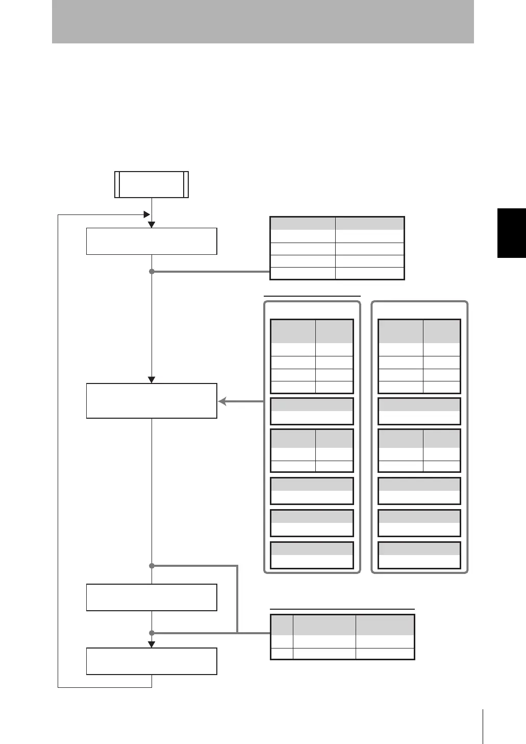
The following shows an example of processing flow during measurement and the data
to be used when feedback processing is performed under the following conditions:
• The Air Clean Unit (ID:1) is controlled based on the larger value of the Air Particle
Sensors on channels 1ch and 2ch.
• The Air Clean Unit (ID:2) is controlled based on the average value of Air Particle
Sensors on channels 3ch and 4ch.
Measurement result calculated
for each measurement time
Measured air volume level
calculated based on feedback
parameters
Measurement result
Air Particle Sensor
1 3500
Measurement result table (example)
Calculation method
Target level
Feedback type
MAX
1000
Constant
Control air volume level value
is sent by communications.
Start of
measurement
Area 1
Low power air volume level
3
2 2000
3 2500
4 3100
Calculation of control air volume
level value for each area
Enabled/
disabled
1ON
2ON
3 OFF
4 OFF
Air Particle
Sensor
Channel
Enabled/
disabled
1ON
2 OFF
Air Clean Unit
ID
Calculation method
Target level
Feedback type
AVE
1000
Constant
Area 2
Low power air volume level
2
Enabled/
disabled
1 OFF
2 OFF
3ON
4ON
Air Particle
Sensor
Channel
Enabled/
disabled
1 OFF
2ON
Air Clean Unit
ID
Calculation of control air volume level value
and measurement result for control (example)
1 3500
2 2800
Measurement result
for control
Area
Control air volume
level value
5
3
Setting values
to be used
3basic.fm43ページ2007年6月28日 木曜日 午前9時18分

 Loading...


