Intersection Equipment Installation Instructions
12
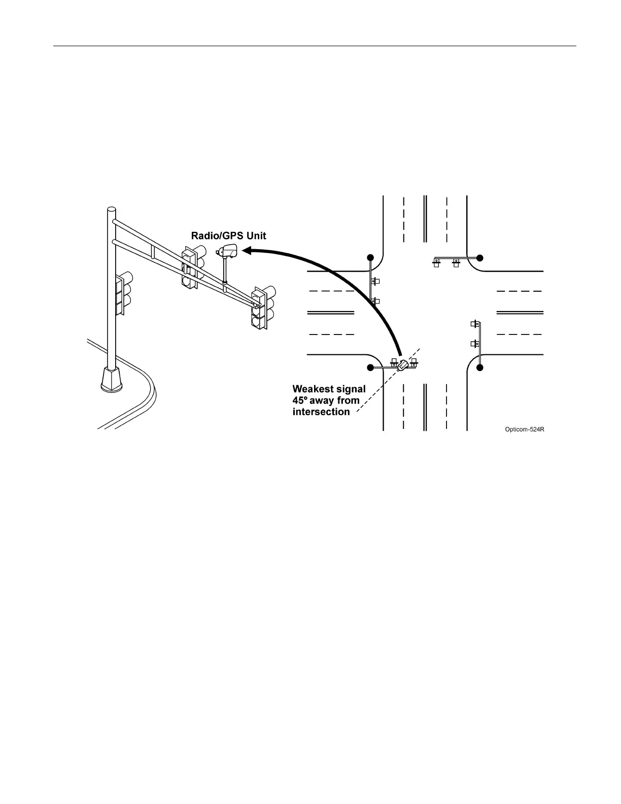
Figures 3-2 through 3-4 show typical installations of the Opticom™ GPS System Intersection Model 1010
Radio/GPS Units.
Figure 3-2 shows a Model 1010 radio/GPS unit installed on a mast arm. The radio/GPS unit should be
mounted level and higher than the mast arm pole, if possible. Place the unit as far out over the intersection
as possible and still provide good coverage down the cross streets.
Figure 3-2. Mast Arm Installation Model 1010