Opticon
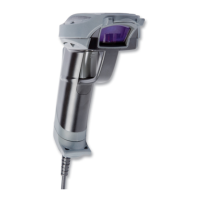
OPR 3201
Specifications Manual
5
14.3. Vibration Strength (without packaging) ............................................................................. 38
14.4. Vibration Strength (with individual packaging) .................................................................. 38
14.5. Dust and Drip Proof........................................................................................................... 38
14.6. Cable Strength ..................................................................................................................38
14.7. Cable Bending Test........................................................................................................... 39
15. Reliability................................................................................................................................... 39
16. Trigger and Read Options ....................................................................................................... 40
16.1. Auto Trigger Overview ...................................................................................................... 40
16.2. Stand Detection.................................................................................................................41
16.3. Auto Trigger Settings ........................................................................................................ 41
16.3.1. Enable when Scanner Inserted in Stand .................................................................................41
16.3.2. Enable Auto Trigger All the Time .............................................................................................42
16.3.3. Only Trigger Manually..............................................................................................................42
17. Regulatory Compliance ...........................................................................................................43
17.1. Laser Safety ...................................................................................................................... 43
17.2. Product Safety................................................................................................................... 43
17.3. EMC .................................................................................................................................. 43
17.4. RoHS................................................................................................................................. 43
18. Safety......................................................................................................................................... 44
18.1. Shock ................................................................................................................................ 44
18.2. Temperature Conditions.................................................................................................... 44
18.3. Foreign Materials .............................................................................................................. 44
18.4. Other ................................................................................................................................. 44
19. Mechanical Drawing................................................................................................................. 45
Table of Figures
Figure 1: Ambient light immunity.............................................................................................. 9
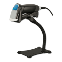
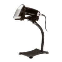
Figure 2: OPR 3201 configuration .............................................................................................. 10
Figure 3: AC adapter 1 ............................................................................................................... 12
Figure 4: AC adapter 2 ............................................................................................................... 12
Figure 5: Laser scan tilt and curvature ....................................................................................... 13
Figure 6: Depth of field ............................................................................................................... 15
Figure 7: Pitch ............................................................................................................................ 16
Figure 8: Curvature..................................................................................................................... 17
Figure 9: Interface circuit ............................................................................................................ 19
Figure 10:Character format (same for both sending and receiving) ........................................... 19