Version 1.1.1 - 2021-1-25 25Translation of original instruction
MB4 EN
MB4_GB_4.fm
4 Operation
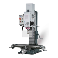
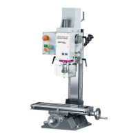
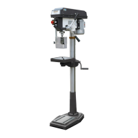
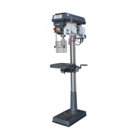
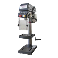
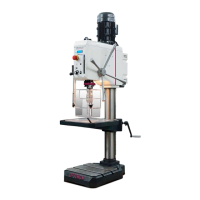
4.1 Control and indicating elements
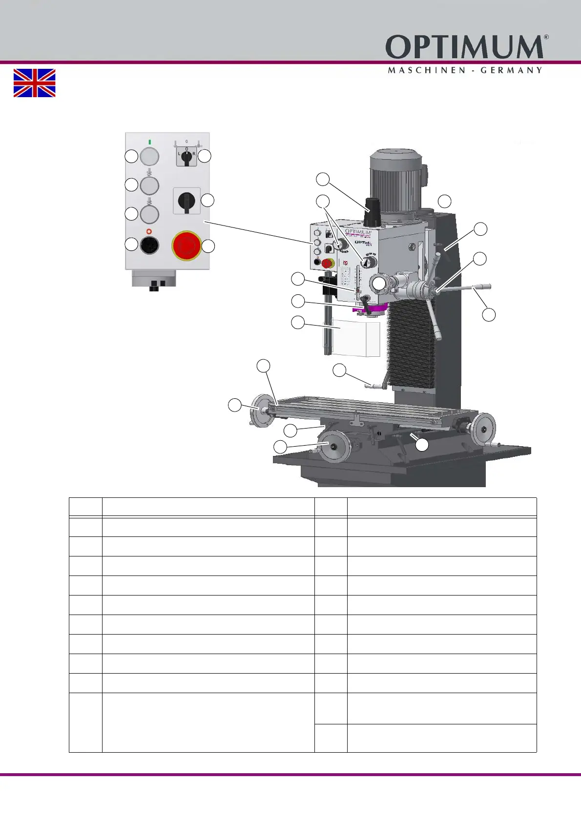
Item Designation Item Designation
1 Draw-in rod cap 2 Rotary selector switch gear stage
3 Meter rule with scale 4 Spindle protection
5 Clamping screw drilling-milling head 6 Star grip for spindle sleeve feed
7 Activation of the fine adjustment 8 Fine adjustment of spindle sleeve
9 Milling head height adjustment hand crank 10 Clamping lever for spindle sleeve
11 Adjustable limit stops 12 Saddle slide Y axis hand crank
13 Clamping lever 14 Cross slide X axis hand crank
15 Operation control light 16 Push button spindle rotation clockwise
17 Push button spindle rotation CCW 18 Push button spindle rotation "OFF"
19 Operating mode selector switch:
Milling
Thread tapping Thread tapping on
page 33
20 Drive step switch
(only with three-phase motors)
21 Emergency switching off