Modular audio matrix
with IP connection
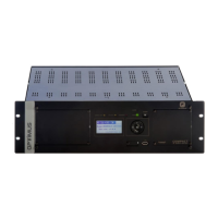
2. FRONT VIEW
(1) GENERAL FAULT indicator light. Yellow LED system
alarm indicator.
(2) SYSTEM FAULT indicator light. Yellow LED internal
equipment error indicator.
(3) EMERGENCY indicator light. Red LED emergency
indicator. Remains illuminated while the system is in
Emergency Mode.
(4) Buzzer. The COMPACT incorporates a buzzer that
generates an acoustic signal when an alarm is received.
(5) POWER indicator. Indicates that the unit is receiving
power.
(6) STANDBY push-button. The unit enters in low
consumption mode and turns off the music
programmes.
(7) Navigation keys and OK/CANCEL selection
(8) Front blank plate. Allows adding ME-200B module
(Fireman’s panel and voice alarm manual control).
(9) Display.
(10) CONSOLE connector. Mini USB connector. Allows
monitoring the system. Only specialised personnel.
(11) Front USB for inputting music
(12) Internal jumper for deactivating the acoustic alarm in
SYSTEM FAULT errors (see section 14).
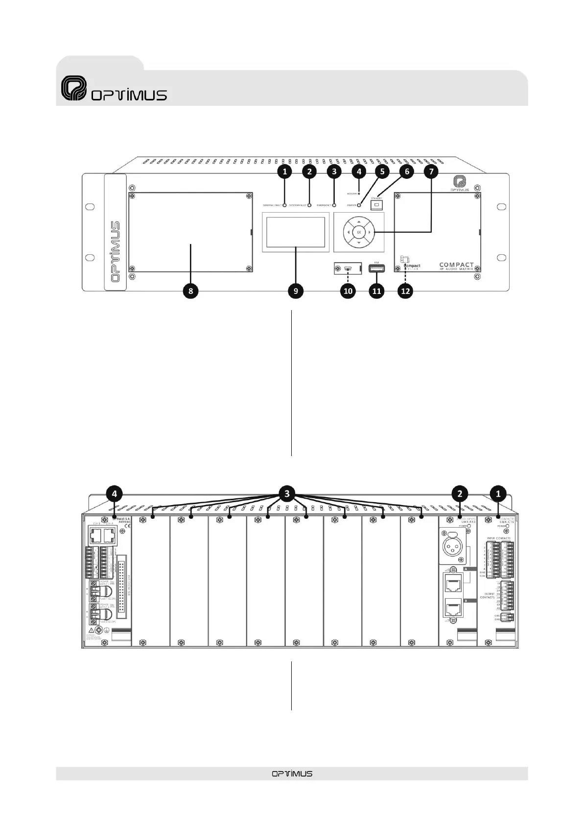
3. REAR VIEW
1) Slot 1 – Card UMX-C16. Input and output contacts card.
See section 7. UMX-C16.
2) Slot 2 – Card UMX-EA3. Card with 2 audio inputs. See
section 8.UMX-EA3.
3) Slots 3 to 10 – Blank plates. Allow expanding the system
with cards UMX-C16, UMX-EA3, UMX-2M3, UMX-2SA,
UMX-2SB or UMX-MC6.
4) Power and control module. See section 3.1.