Modular audio matrix
with IP connection
CONTACT B
REFERENCED TO
GROUND
SW2. UNION BETWEEN THE NEGATIVE SIDE
OF THE POWER SUPPLY AND THE CHASSIS
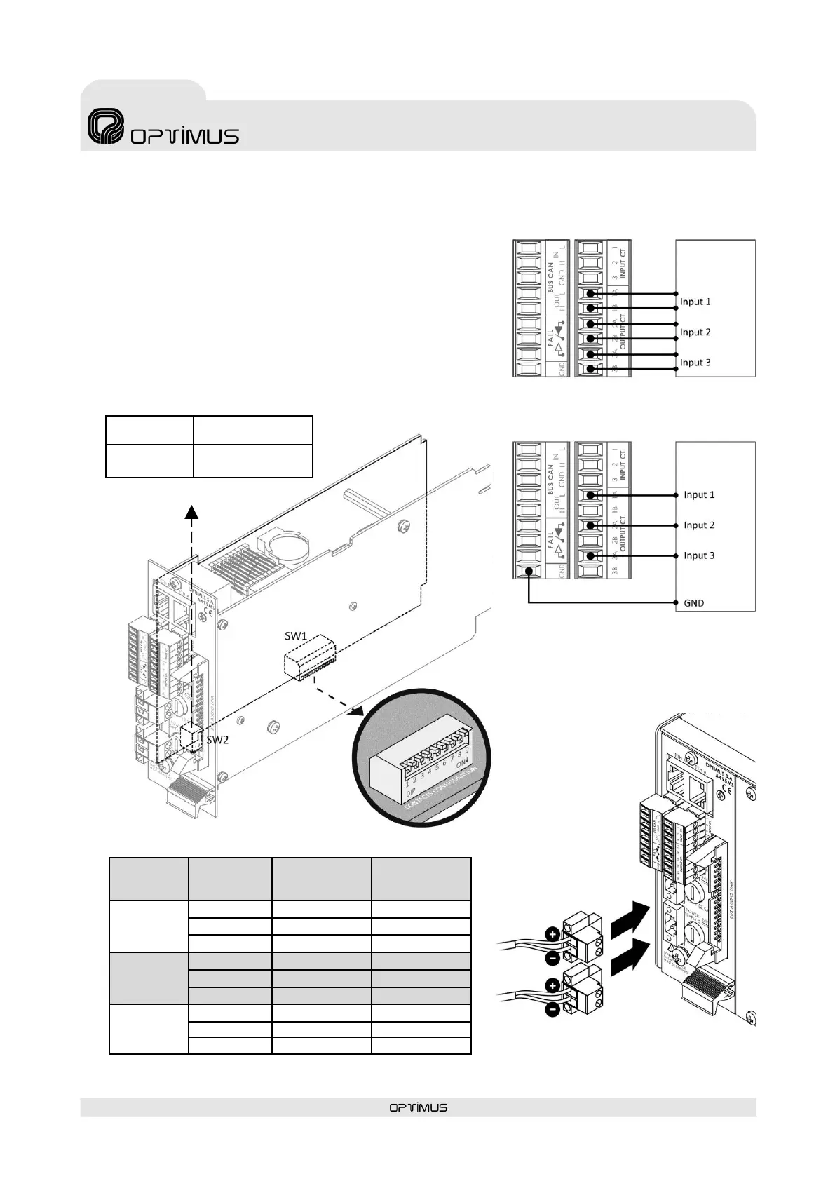
Figure 8
CONNECTION OF THE OUTPUT CONTACTS.
AS DRY CONTACTS
Figure 9
CONNECTION OF THE OUTPUT CONTACTS.
AS CONTACTS REFERENCED TO GROUND
DIPSWITCH 1 ON*
DIPSWITCH 2 ON*
DIPSWITCH 1 OFF
DIPSWICTH 2 OFF
Figure 7
SW1. CONFIGURATION OF THE OUTPUT CONTACTS
7) OUTPUT CT Contacts
Incorporates three output contacts. Each contact has two terminals (A
and B) that are configurable using internal DIPswitches as dry contacts
or referenced to ground. To configure see figure 7.
The functionality and de-energized state (NC/NO) are configured
through the Call Point software. They may be configured as general
purpose contacts or in the evacuation system as fault notification
contacts, Emergency Mode indicator activated...
To connect as dry contacts follow figure 8. If contacts referenced to
ground are desired, follow figure 9.
Figure 11
SECONDARY POWER
Figure 11
SECONDARY
POWER